Cross posted from the original Pinside thread, this is one of many posts regarding my third homebrew pinball machine, creatively nicknamed 'P3'
Finally got the lights all working, and coded a simple attract mode animation for them. Originally I was trying to use an existing server I found for controlling ws2812 leds, but it kept crashing and wasn't very suited for pinball animations, so I coded a simple server myself which just handles a light being on, flashing, or pulsing, with settings for frequency and phase. I think I will need to tweak my colors a bit though. Not sure if it's because of the specific leds I got, or the way the opaque white inserts are coloring it, but everything feels a bit 'pastel'...
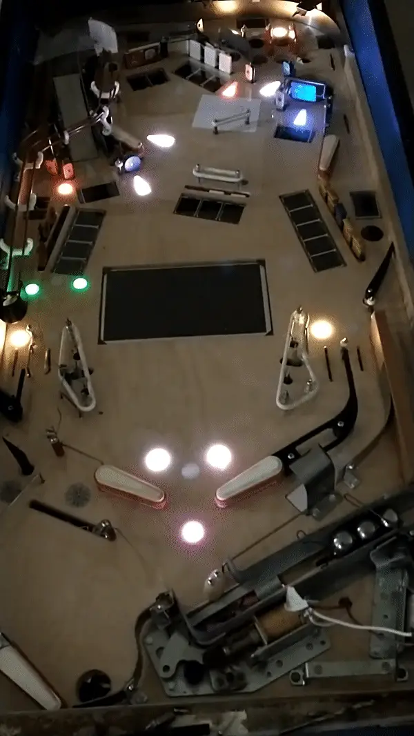
The downside to doing all your leds as one giant strip, I guess, is that if you want to change them later it's more complicated. And of course, once I got everything together here, I realized I'd forgotten to install a light for the lower playfield diverter. So I guess at some point I'll need to cut a bit from my left over led strip, attach that there, then cut my existing strip somewhere, and run the data line over to the new led and back again.
I'm also thinking about maybe having a sort of 'wizard mode' accessible after you get all the main hands (at least straight, flush, full house, since technically those cover all the 'lower' hands too. maybe four of a kind, but it's hard to guarantee there's ever a deal with 4 of the same card), so it'd be nice to have a few more inserts in the barren center area between the screen+slings for that. Just when I thought I had all the lights/etc figured out!
Cross posted from the original Pinside thread, this is one of many posts regarding my third homebrew pinball machine, creatively nicknamed 'P3'
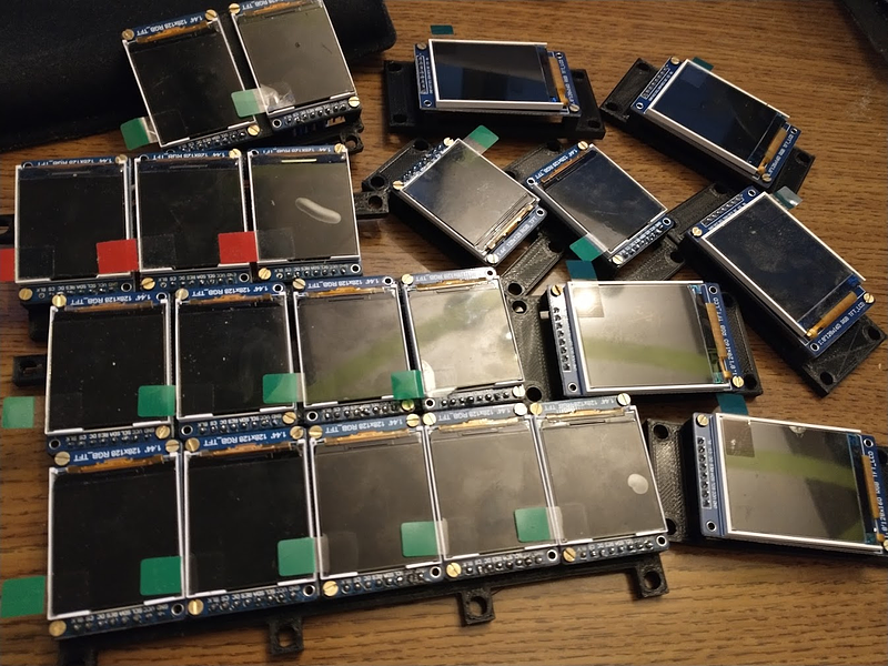
I'd been getting tired of using the projector for everything, and with the lights taking away half of its use, I figured it was a good time to get to work on the other part of that: the cards themselves. I'd realized early on that having all the cards just printed on the playfield, unchangeable, would have a possibility for people finding certain cards to go for every time which would make the game less fun, and having the projector able to deal a random set of cards onto the playfield solidified that worry. And then I found some cheap LCD displays on ali express while searching for the main screen I installed before 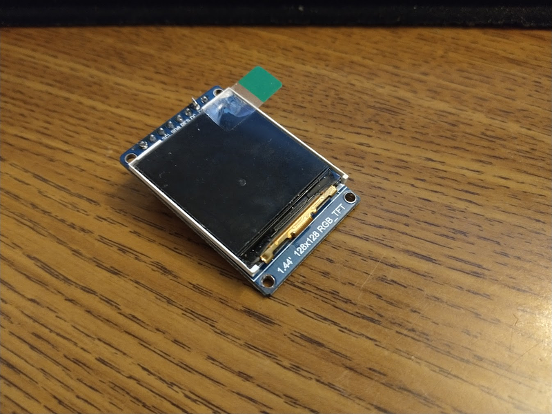
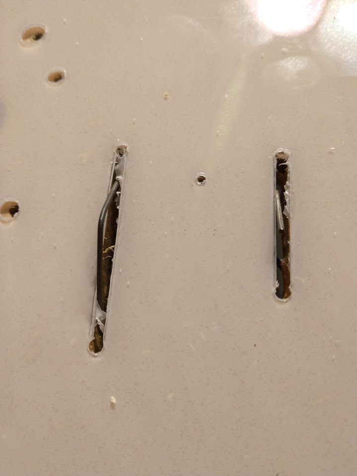
Turns out they were slightly narrower than the spacing on the drop targets: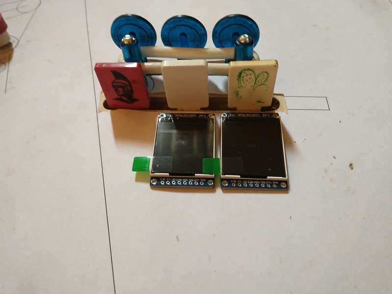
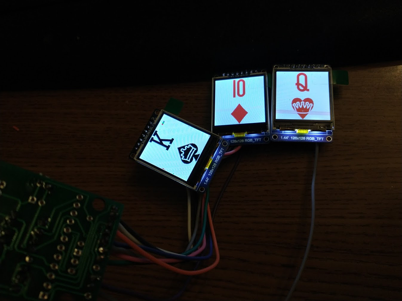
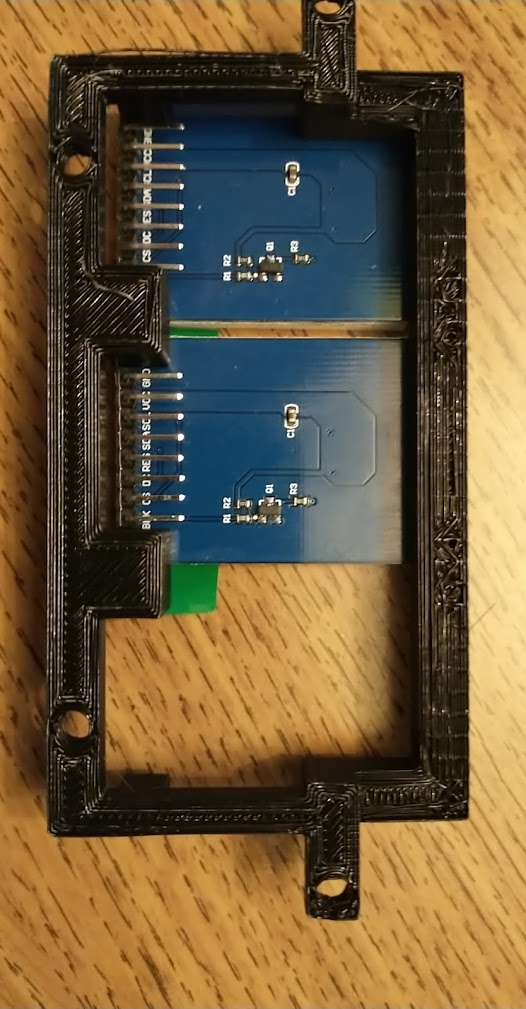
Thanks to the provided example code it wasn't very hard to get one to display a card using a raspberry pi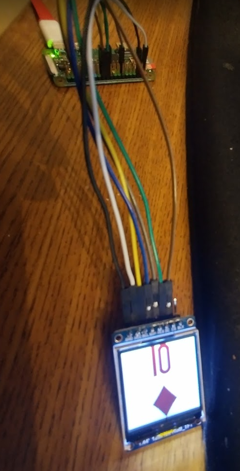
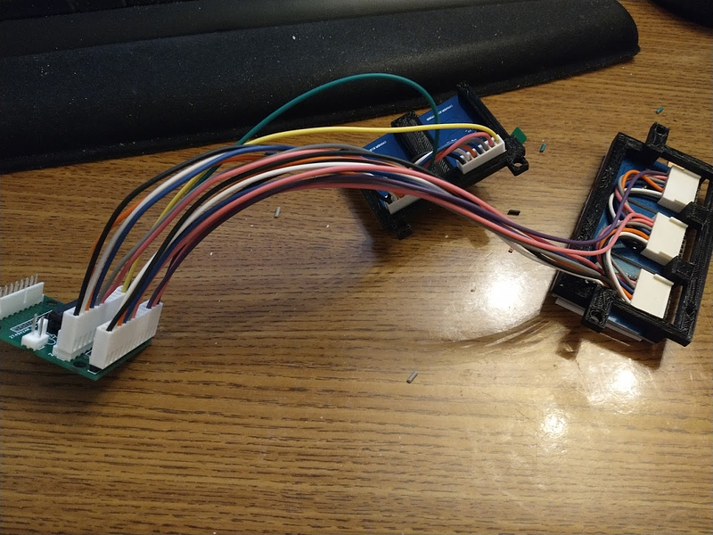
But could you drive more than one easily? I made a little board that had a shift register on it to control the CS line of the display, so that I could theoretically wire up to 8 displays to it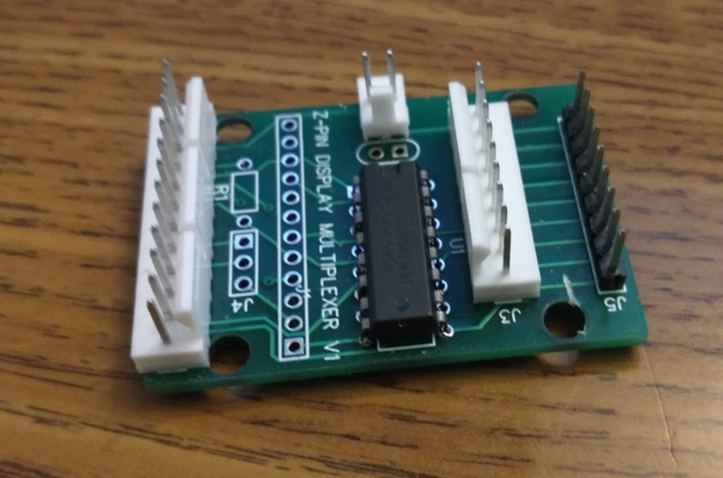
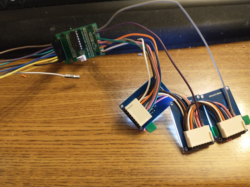
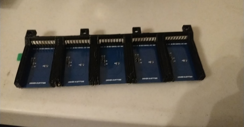
So far so good! Now, could I fit those displays in front of the targets? I did some measurements of the 3 bank in the middle and printed a bracket
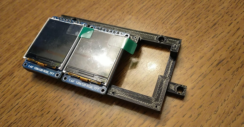
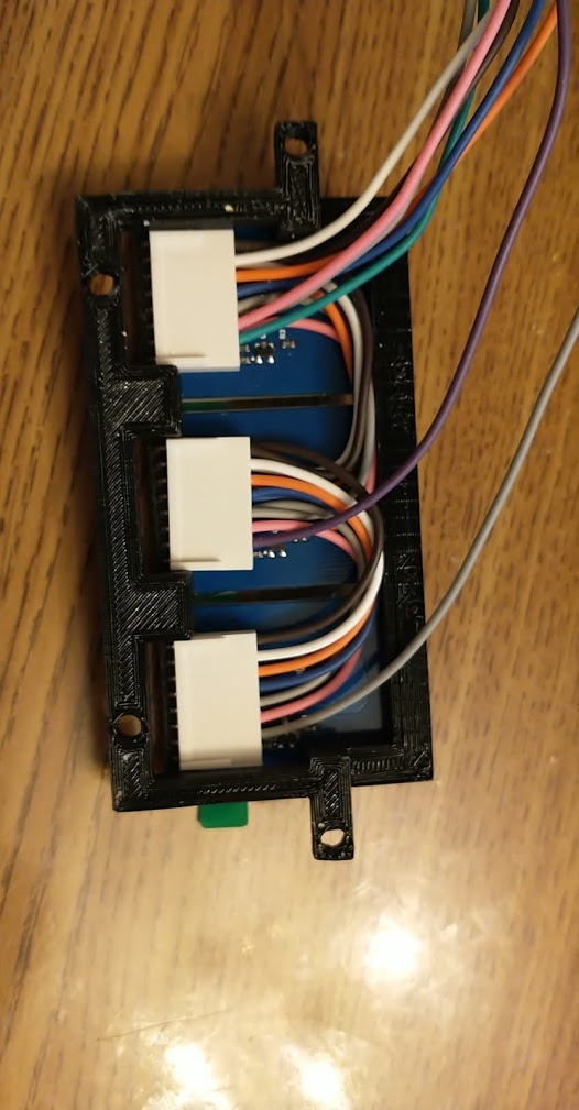
And they fit! barely.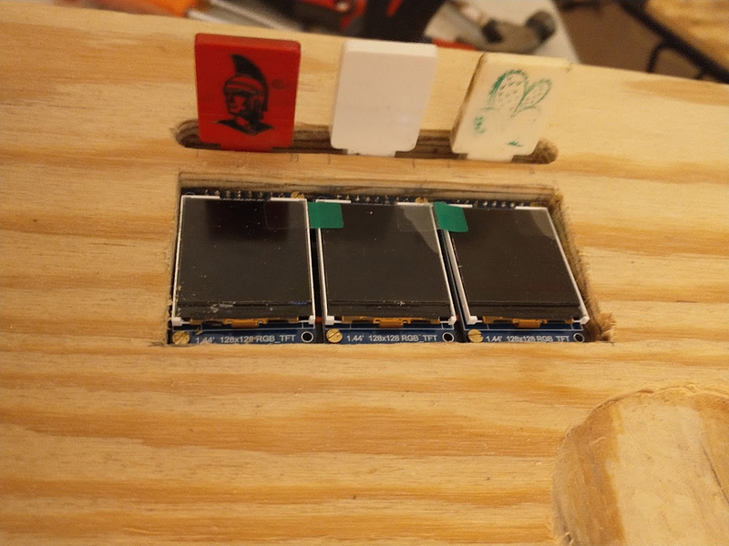
I programmed a simple tcp server to control them, and hooked the 3 displays into the game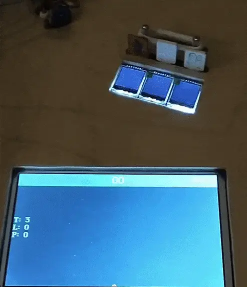
Alright, proof of concept complete. Time to go way too far with this.
I'll need to custom make a bracket for every bank in the game, since they're all different manufacturers+sizes
And since I'm already getting into this, why not throw some other single displays around the playfield?
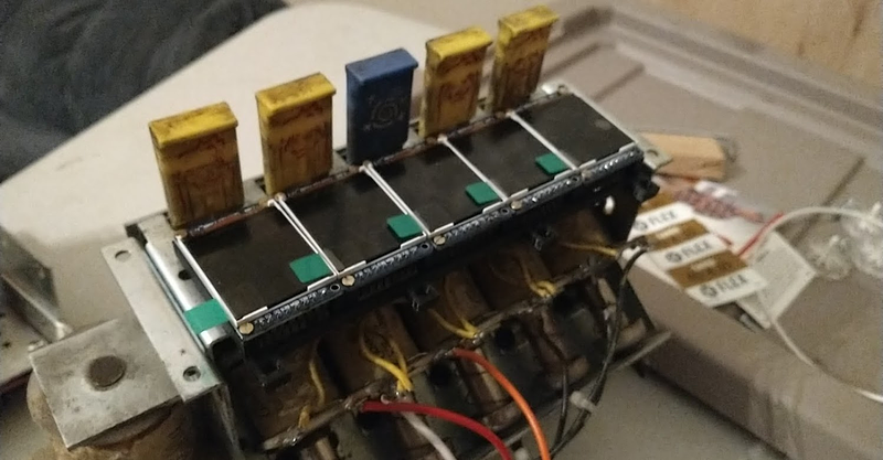
Now, can I actually drive them all? No. I lose signal around the fourth board. A lot of learning about signal integrity and I've got another version of my board with some termination resistors and a buffer chip to redrive the signal between each board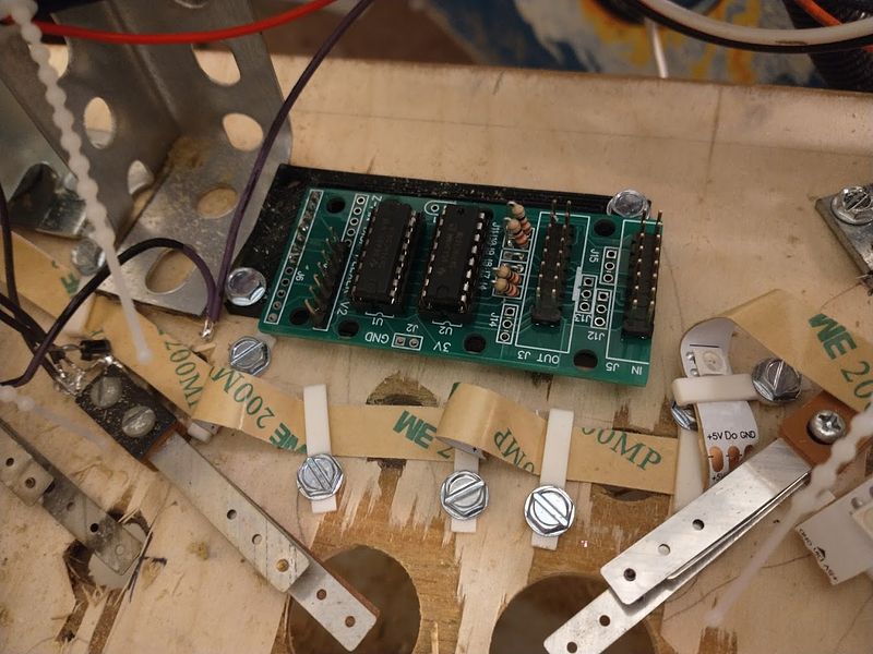
And with that, I can barely get all my displays to work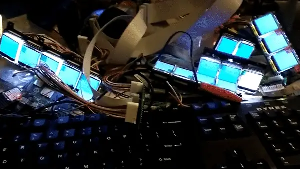
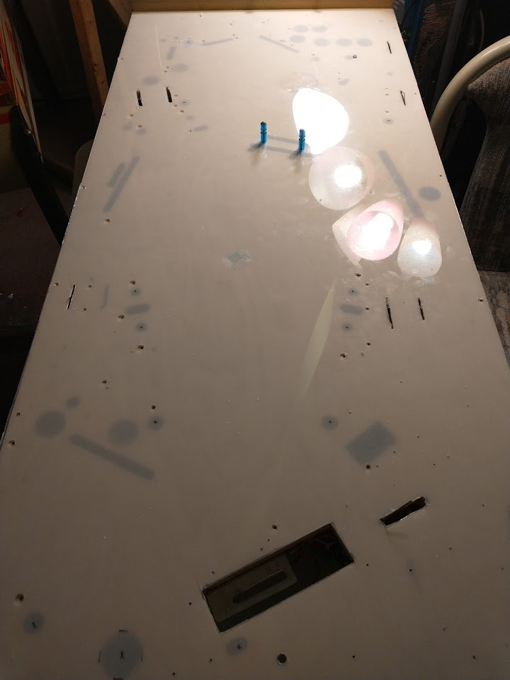
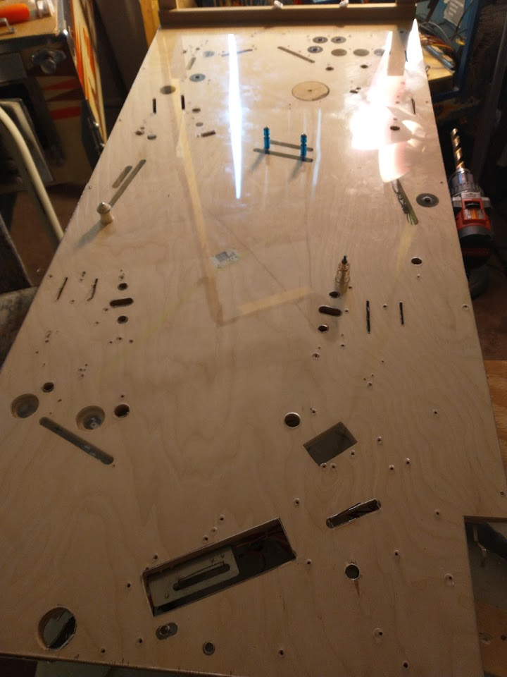
So I cross my fingers and cut a lot of big holes in my playfield. The amount of missing wood at this point is starting to concern me a bit, but it seems to hold up okay when the side rails are attached. 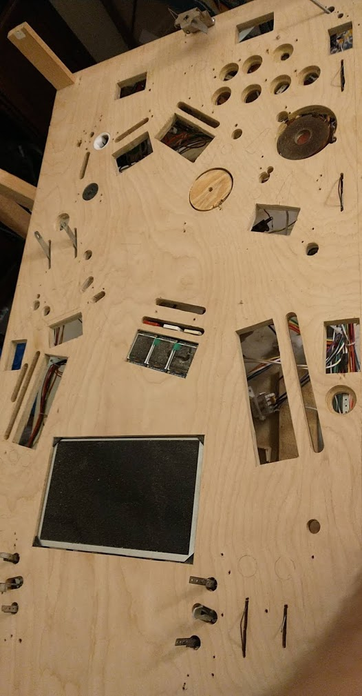
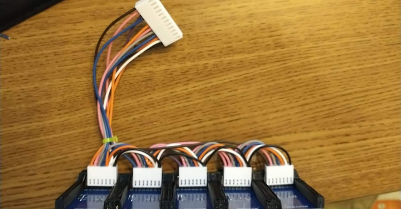
Wiring them up is also fun. So many ribbon cables! Almost looks like a Spooky game...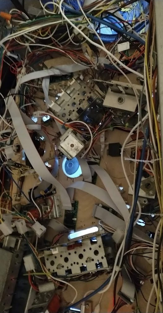
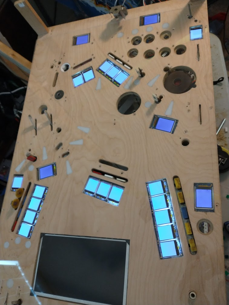
And once I finally got the whole playfield reassembed...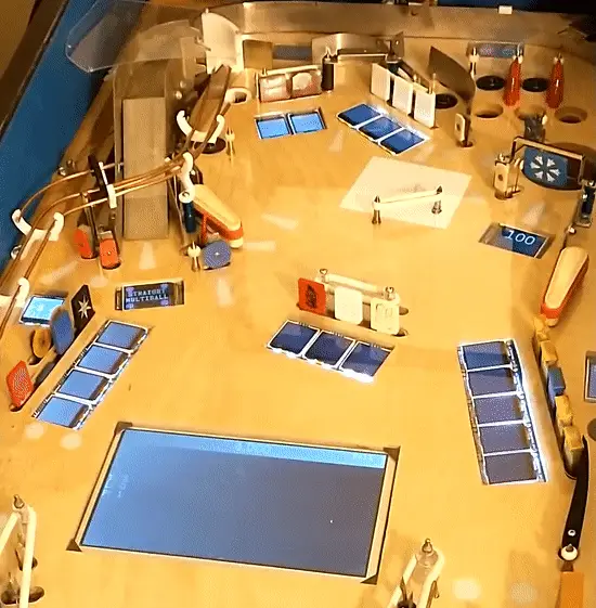
Success!
Cross posted from the original Pinside thread, this is one of many posts regarding my third homebrew pinball machine, creatively nicknamed 'P3'
Still working on a bunch of stuff so I don't actually have any top side pictures yet but..... light!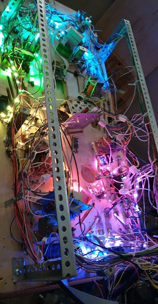
The funny side effect of just trailing a light strip around the playfield is actually looks cool underneath too.
I ended up using 126 LEDs worth of 30/m strip to reach all ~30 inserts on the playfield. Besides from a few places where I didn't plan for lights and had too many mechs in the way, it was pretty easy to mount the strip over the the holes. The budget pack of clips I found are a bit too big, so there's still a bit of back and forth play, but I don't think there'll be enough movement to cause any issues. 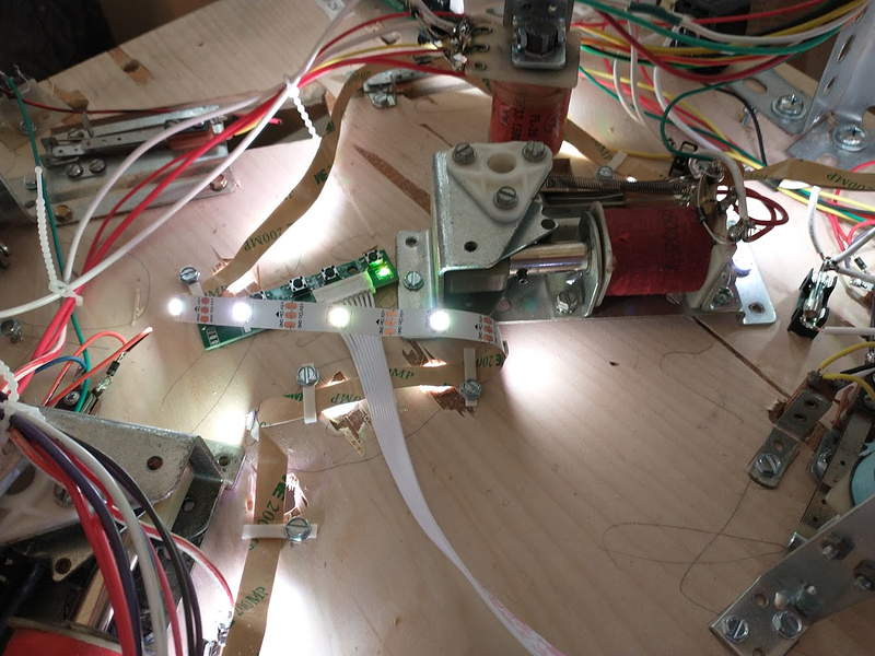
I hooked the strip up to a dedicated 5v line+fuse coming from my ATX PSU, and it seems to be lighting fine with just that power coming in at one end (I was sorta expecting needing to provide more power somewhere along the length), even with all the lights on (which will never happen in practice). I had to make another little adapter board for my RPi-powered MPU to add in a 3V - 5V level shifter since the RPi only puts out 3V, but that seems to be fine for driving the whole strip, with an added 4ft of wire between the board and the beginning of the strip. Time will tell whether the electrical noise interferes with the lights once everything is playing, but hopefully they'll be okay (plus I plan to refresh them at 30Hz so any glitches should clear up quick).
Cross posted from the original Pinside thread, this is one of many posts regarding my third homebrew pinball machine, creatively nicknamed 'P3'
Got the inserts from PBR, luckily they're the same size I was planning on, so I went ahead and cut all the arrows. 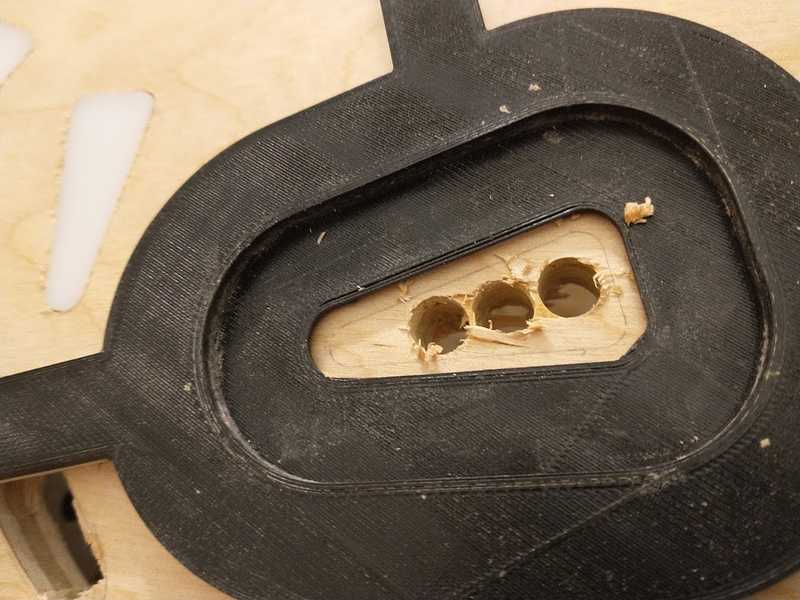
Midway through I stumbled upon this technique, drilling three holes through first, then routing out the rest using the guide, which allows me to do all the routing in one pass (before it was three passes since I kept needing to stop and remove all the dust, etc). Then once it was cut and the insert test-fitted, I'd take the guide away and hand route between the three holes to leave a good open area in the center for the light.
I was hoping that the circular inserts would match up with my forstner bits, but not all of them did. The smallest one (5/8?) are perfect, a nice snug fit, but the 3/4" are just loose enough that they'll fall out from gravity if there's any vibration. I'd like to get these all press-fit if possible so I don't have to worry about gluing them, so I'm going to try to make another router guide for the 3/4"
Cross posted from the original Pinside thread, this is one of many posts regarding my third homebrew pinball machine, creatively nicknamed 'P3'
Got the LED strip today. Was surprisingly easy to get working using adafruit's python library, worked the first time. Sadly I don't want to use the python library so I'll need to explore alternatives for integrating it with the rest of the code. I did some experiments with inserts. The circular ones lit up fine, but the larger ones like the arrows had a bit of coverage issues.
It's hard to get good pictures of leds lit up, but
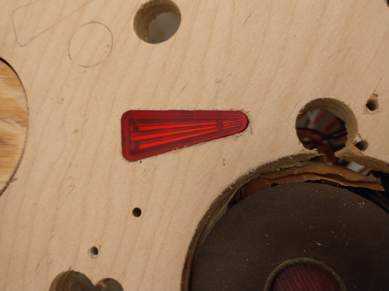
Here's a clear triangle insert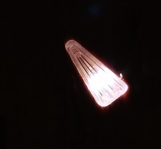
And here's an opaque one 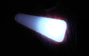
The clear one lit up a bit more evenly, but it didn't really look that good, you could clearly see the hot spot where the led was located. Surprisingly I think the opaque one looked better overall, and other colors seemed less washed out, which is nice since that's probably my only option...
I then played around with led placement. Putting it more towards the center or ends didn't help much; the ends were still pretty dim. What did help was cutting a bigger hole. here's a single led, positioned similarly to the previous photo, but with almost all of the insert cut through the playfield instead of just one hole the size of the led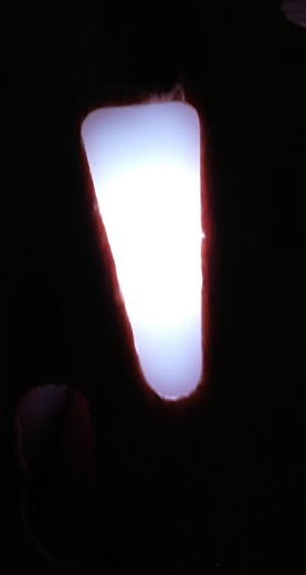
Probably good enough for me. I'll need to come up with a better way to cut those inner holes out, maybe another 3d printed router guide or something.
I also played with two leds under the same insert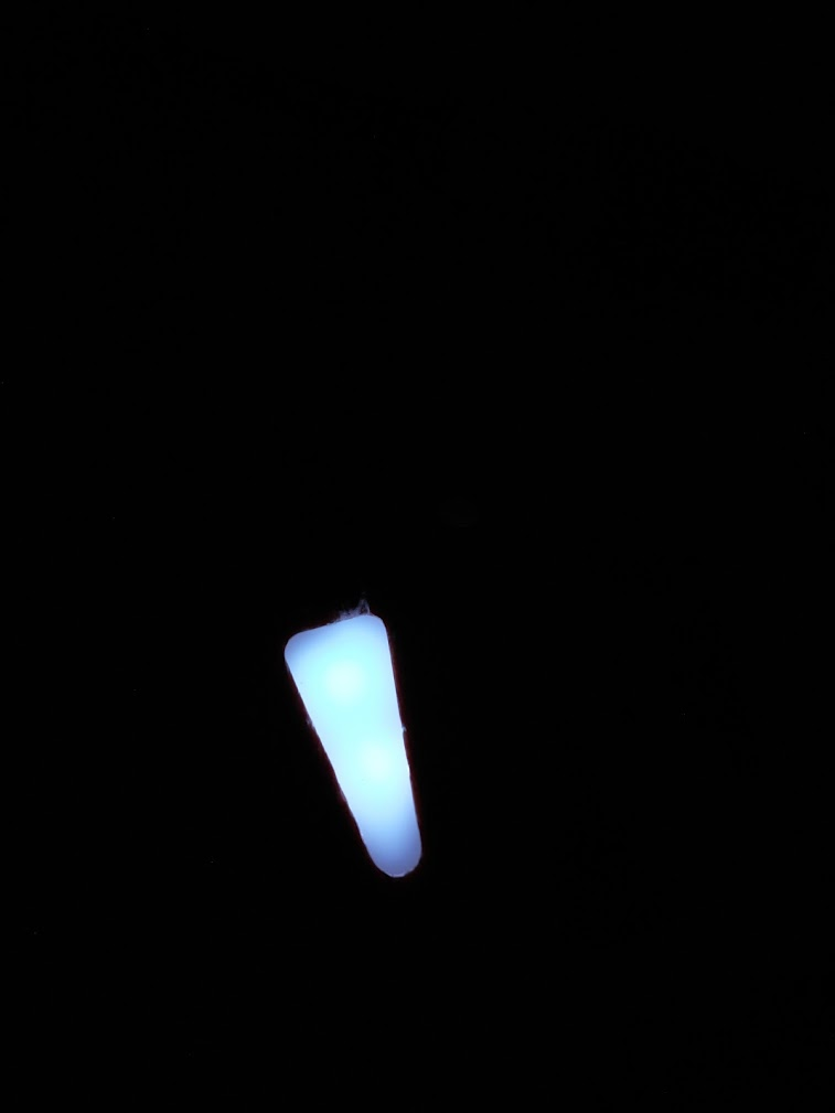
This looks a bit better than just one, but not as good as I was expecting. The hot spots seem more pronounced. I'm not sure if I'll be able to position the strip to hold two leds inside the arrow or not (the clamps haven't arrived yet). This is where a lot of people seem to use multi-led boards, which might be worth it at least for the main shots? I'll have to look around
Cross posted from the original Pinside thread, this is one of many posts regarding my third homebrew pinball machine, creatively nicknamed 'P3'
Since I had the playfield torn down, I figured I might as well install the inserts too. I've got a big bag of random inserts I've collected over the years from different stores, so I started laying them out. 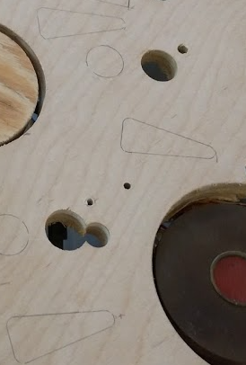 To keep things simple, I used one size of arrow (1.5" triangle) and three circles. I think the circles can probably be done with a forstner bit, but the arrow will need to be done with a router. Taking some advice from
 ![]() Johnsonvillebrat, I designed a guide for my router
Johnsonvillebrat, I designed a guide for my router 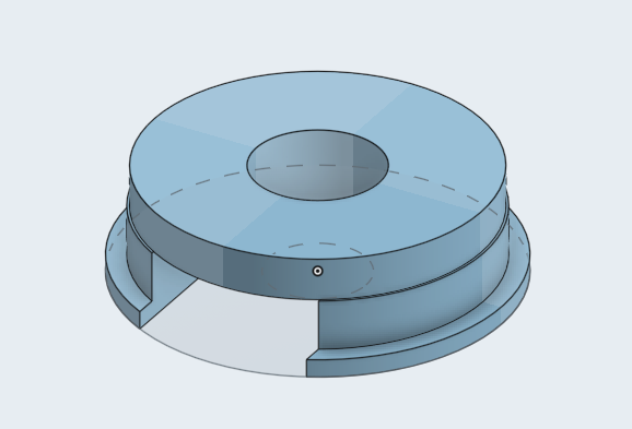
and a guide for the shape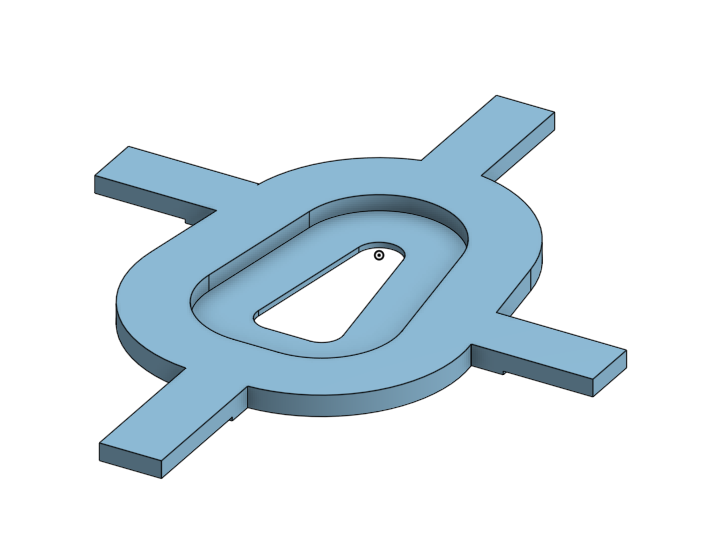
It took about 10 tries to get the guide just right for a snug fit (a big pain, since each print took 3 hours!) but I eventually got it just right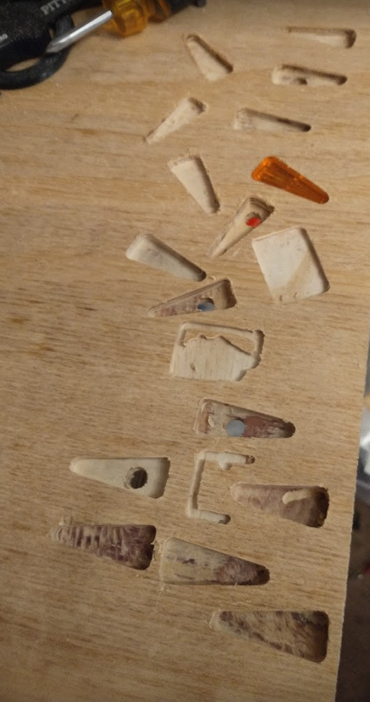
and made my first cut in the playfield
....aaaand immediately ran into an issue.
Can you spot the difference between these two arrows? 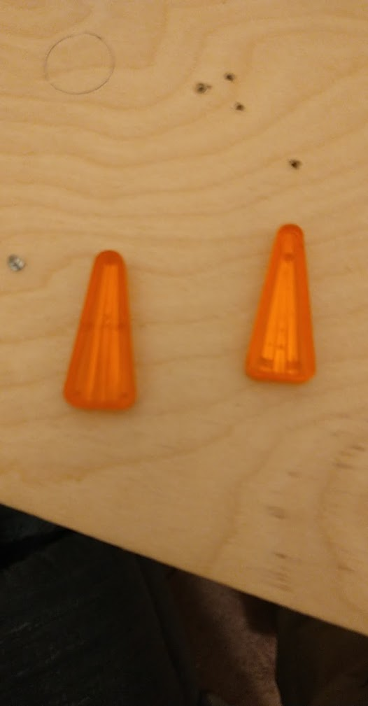
One is wider at the tip! I sorted through my inserts and found out that half of them won't fit the guide I made, which also means I don't have enough of the correct inserts for the playfield. I was planning on making them all clear, uncolored, for RGB lights, but I don't have enough of those. So I went to order more.
...aaaaand no one stocks them! (unless I want to pay $5 each shipped from europe) What? A transparent arrow should be like, one of the most common ones needed. Pinball Life (who has a great selection of inserts for homebrew) has six colors... but no clear. And they don't have any plans for restocking. The best I can find is that PBR has some opaque white inserts available, but I'm not sure how that'll look since every modern game I know of with RGB lighting uses transparent.
Luckily, I had one of those in my assortment, so I figured I'd stick it over an led and see how it compared.
...which made me realize I have no RGB leds. In fact, I have no real plan at all for how to light all these inserts! Back when I was first planning out this electronics system years ago when RGB was still a bit new, I figured I'd just get some 4-legged RGB LEDs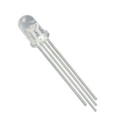 , and then just stick them in a matrix. Except I don't have any boards designed to drive a matrix. And after wiring up the switch matrix, I really don't want to wire up another whole matrix with double the wires. It seems like today everyone is using NeoPixels and other individually addressable, chainable LEDs (well, besides stern, but), so I started looking into what'd be the cheapest, easiest, least messy way to get some of those installed. Luckily when I designed my MPU I added a spare connector for the 3 extra unused GPIO the RPi had, and I made sure that one of those was the DMA pin that's commonly used to drive these LEDs from a Pi, so I think I can drive them. If not I can get a FadeCandy or something. It seems like a lot of people are just buying FAST's individual LED boards, but they're $1.50 each, and need wiring to connect them all. So I ordered 5 meters of addressable LED strip (150 LEDs) off eBay for $15, and some mounting clips for $5. I'm hoping I can just string this through the playfield to reach all my lights, and use the spare LEDs in between as free wiring (just don't turn them on). Maybe that'll work, or not. I can always find a use for 5M of LEDs at worst though.
In the mean time I've also ordered a bunch of opaque white inserts from PBR, since they're cheap and I needed some other parts anyway. Hopefully they light up well. Maybe the opaque inserts will give it a more retro feel? Of course, I don't know if the random opaque triangle insert I had lying around is from PBR or not, so cutting (and thus, reassembling) the playfield needs to go on hold for now until the order arrives so I know whether I need to design a new router guide ![]()
Cross posted from the original Pinside thread, this is one of many posts regarding my third homebrew pinball machine, creatively nicknamed 'P3'
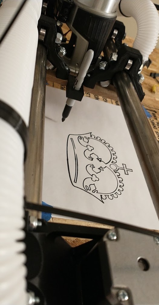
Ran a test cut of one 4x5" area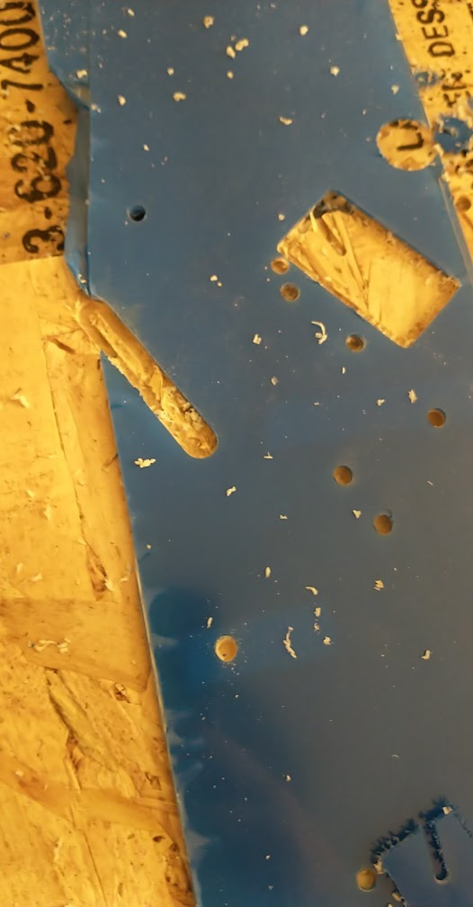
It turned out fine, no obvious issues. 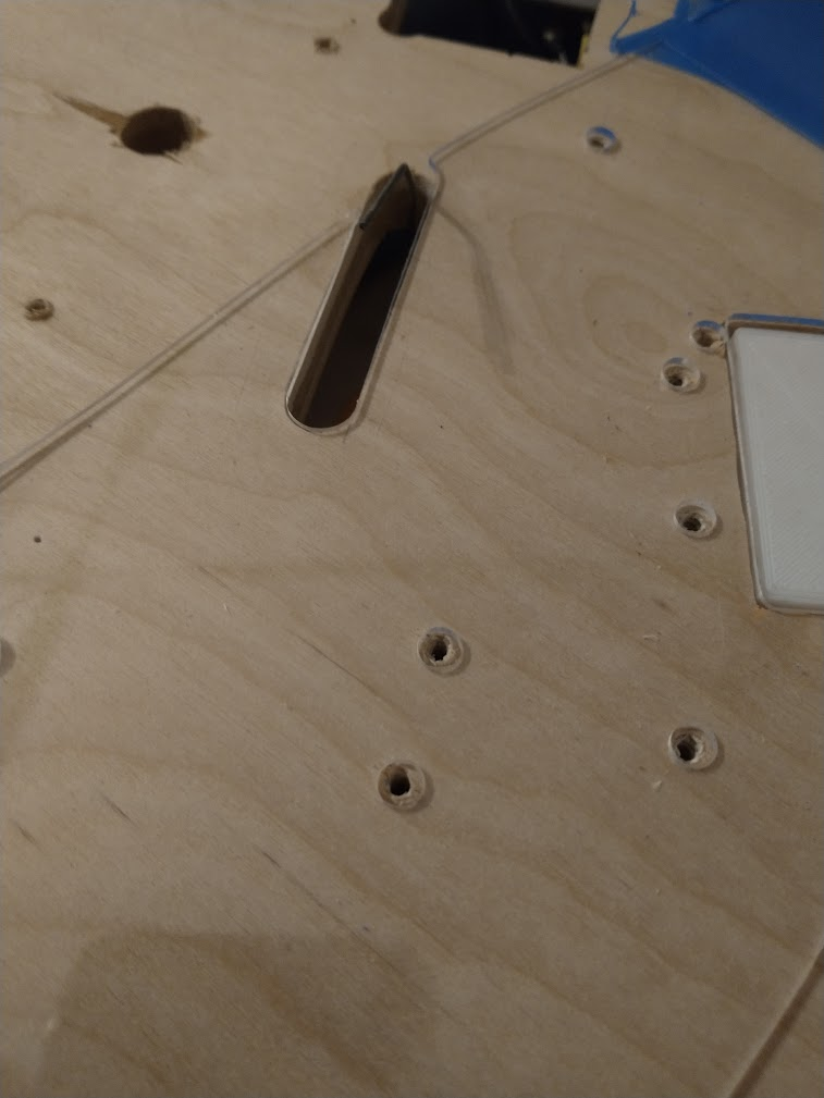
so I went and did the whole thing. I took one of my rough manual cuts, and stuck it down with a bunch of double sided tape. In retrospect I should have used thinner tape, as during the cut I could see the plastic flexing downward before the bit broke through, but it doesn't seem to have caused any issues with the cut.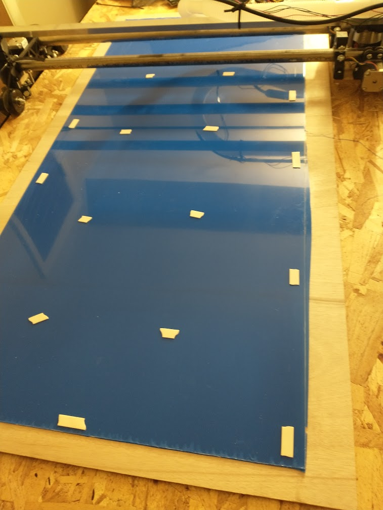
My first time running a real job on the CNC, probably took about 40 minutes. Plastic seems to have come out fine, and it at least fits on the playfield.
 Most of the holes are off center, but not outside the margin of error (I made every hole bigger than needed).
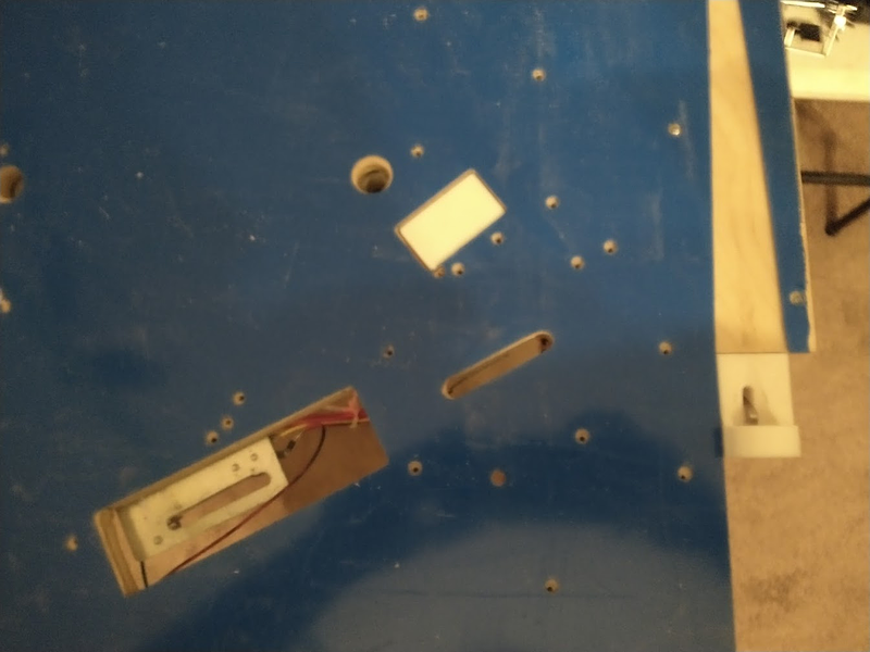
 There's a few places that need some correction, so I need to figure out how to do that. Aligning the plastic perfectly was a big pain, I don't think I could reliably get it matched up again. But I want to avoid doing stuff 'by hand' for risk of cracking the plastic. Maybe I'll need to use the router manually? Or try to run the CNC with manual control. Before I bother with any of that though, I should probably secure this down again and do some more heat tests.
I went in multiple times to try to do the corrections to the layout, but something just wasn't making sense. The corrections weren't all in the same direction, but different parts of the playfield tended to all need correcting in the same direction, and half the time that direction was opposite of how i'd already corrected those points before. In addition, the way I lined up the plastic so that it lined up with holes the closest resulted in it not being parallel with the edges, which didn't make sense either. When I lined it up with the edges of the playfield, right to the corners (where I know it should all match up), none of the holes lined up at all. So I stopped working on that until I could figure out what was going on. I measured various parts of the plastic and the wood playfield, and checked them against my CAD drawings, and they were all accurate. Then I got a t-square out to check if maybe my playfield somehow wasn't square. Nope, playfield was square. But the plastic wasn't! It had a 3/8" skew to it along its entire length. There must have been something wrong with the setup of the CNC causing it to list to the right as it moved up the playfield, so I'll need to figure that out. Never noticed in my test cuts since all of them were smaller. So that plastic is a loss for any real work. But knowing that it's wrong, I don't have to worry about fixing it the right way. So I just got out a router and adjusted all the holes by hand to line up enough. I'll reassemble the playfield on this bad plastic for now to test out the material.
Cross posted from the original Pinside thread, this is one of many posts regarding my third homebrew pinball machine, creatively nicknamed 'P3'
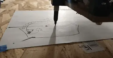
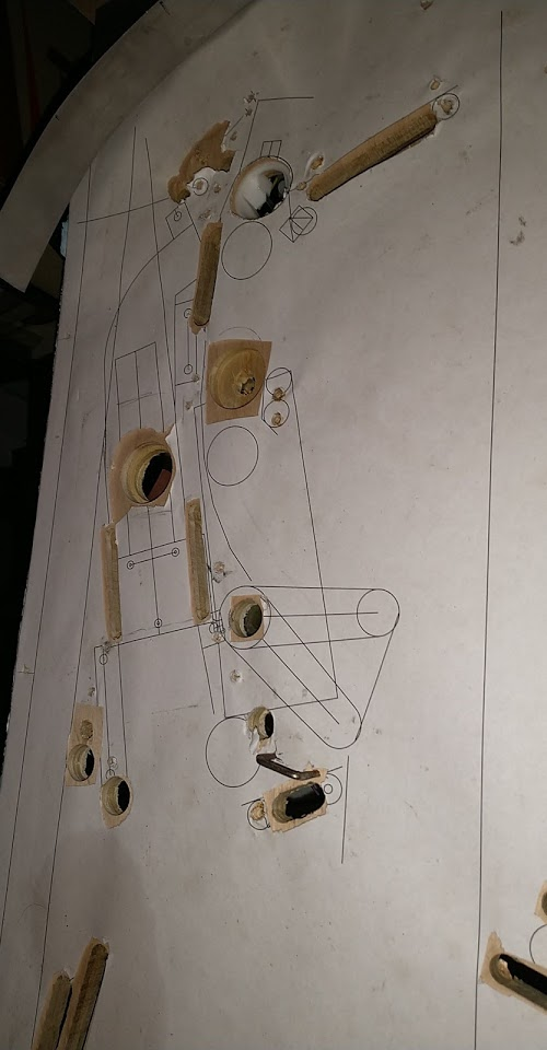
But before I can cut some new stuff, I need some drawings to cut! I took my scan of the original playfield, and converted it back into a cad drawing (what a pain!). Then I got that printed out on paper at 1![]() scale again, tore down the playfield, and laid the paper down on the playfield to verify everything, since I wasn't sure if the scans would be "square".
scale again, tore down the playfield, and laid the paper down on the playfield to verify everything, since I wasn't sure if the scans would be "square".
Sadly you can't see through paper (it would have been amazing to get this printed on something clear but as always I'm being cheap), so I had to use a small screw to search out all the holes in the playfield again for comparison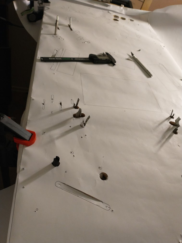
Some parts were spot on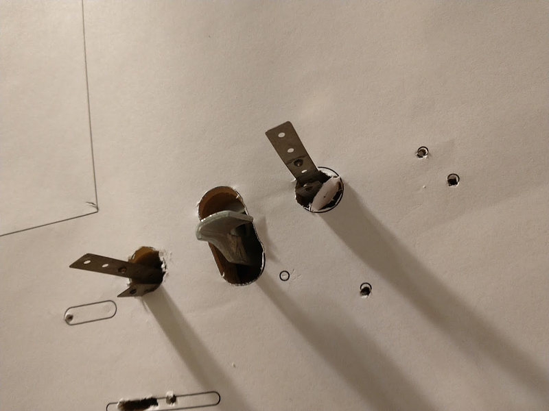
Some were off, but very consistently so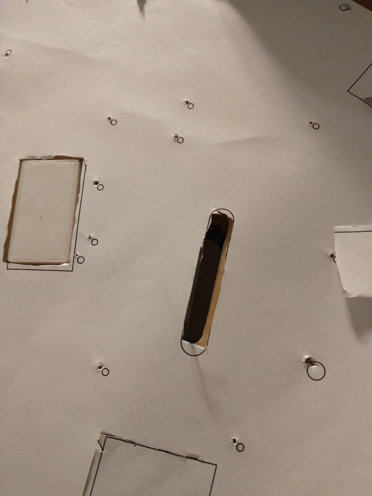
And some things were so far off I don't know what could have happened... 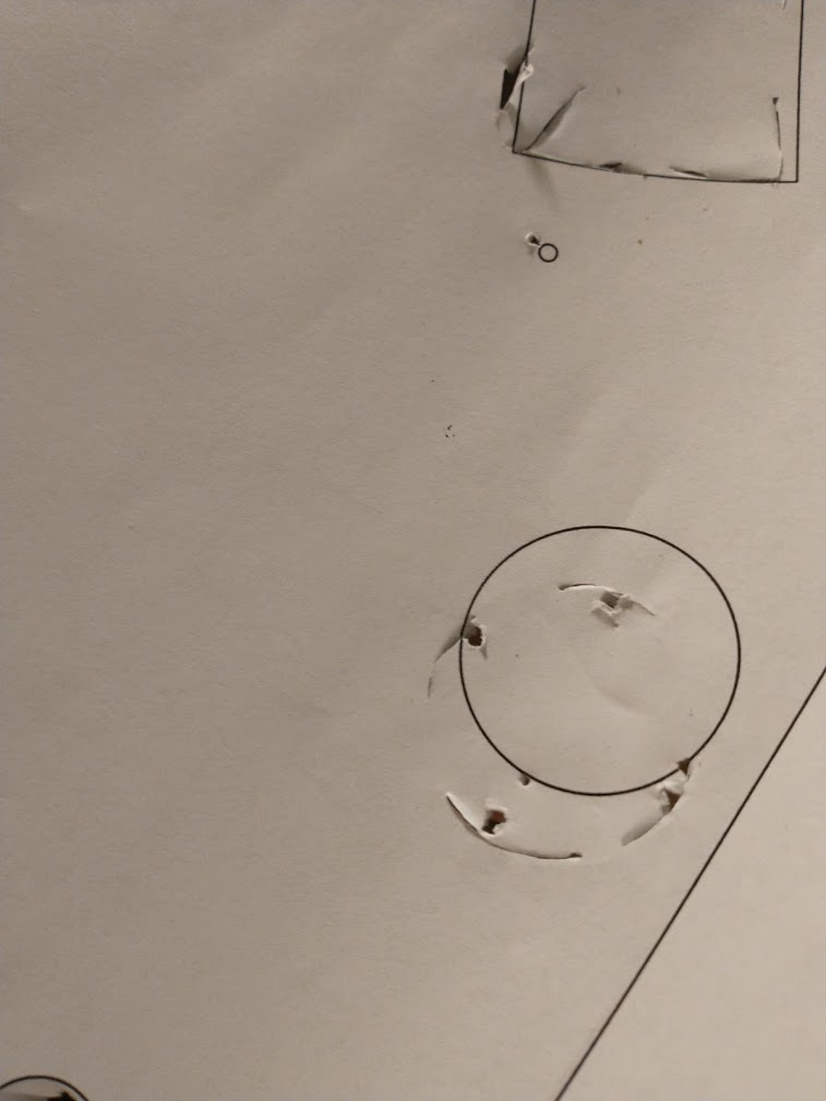
Overall, the stitching seems to have worked pretty well, but not good enough to really be a go-to thing. In the future I'll need to be more vigilant about cutting stuff exactly matching the cad, and adjusting the cad as I go when anything diverges to prevent this.
I spend most of my day off today going through every hole again and manually adjusting my cad drawing (which the paper was printed from) to account for the discrepancies, so hopefully I'm now good to go. I'd like to avoid having to get another throwaway paper printed to verify all my changes, and I've got 3 sheets of acrylic ready to go, so I'm tempted to do a few test cuts on leftover stuff, then just get cutting and see how I do. Probably not the smartest thing to do but at some point you've gotta stop preparing and just jump in, and the cost of failure is theoretically pretty low (or it would be if I could find any reliable source of plastic locally, grr)
Cross posted from the original Pinside thread, this is one of many posts regarding my third homebrew pinball machine, creatively nicknamed 'P3'
Two months of no real progress on the game, but: I've got a CNC router! 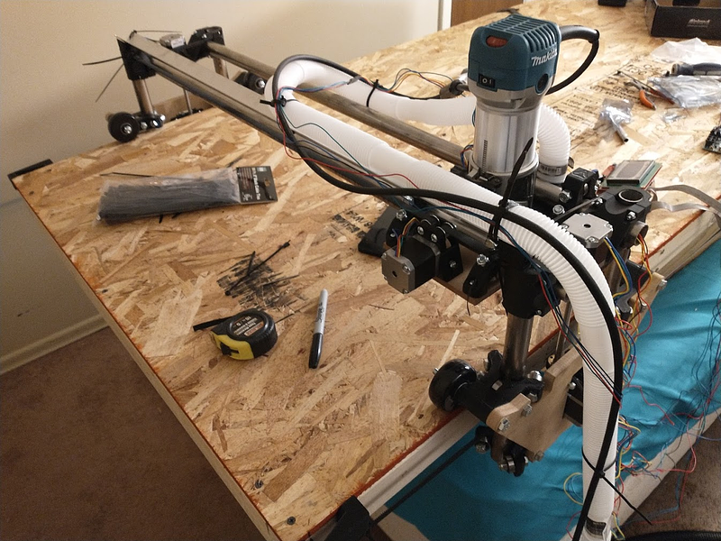
It's... currently sitting on top of the bed in my spare bedroom, because I horribly underestimated how big it would be. But that's fine, not many guests during COVID. I haven't done any really big serious work with it yet, but it seems to work fine for my small tests I've run so far, so I don't think anything should change much.
I did some test cuts using a straight edged router bit (not sure the correct term for this), which was recommended for cutting plastics (since it doesn't have a helix to pull up the material). With a spare bit of lexan, it didn't do too well, sorta ripping up the edges and melting them a bit, similar to the issues I had cutting my lexan by hand with a drill. I got a sheet of 1/16" acrylic and tried that, and it cut much better. Not perfect, but definitely presentable. The only issue is that acrylic has a tendency to crack and shatter randomly. The router bit hasn't caused any of that yet, but when doing a whole playfield it could potentially cause an issue. I also tried another scrap of plastic I had on hand (which I think is PET-G, but I didn't label it), and it cut super nice. I'm trying to source some PET-G sheets locally to test out but I haven't found anything so far, so I'm gonna go ahead and try the thicker acrylic first. Acrylic also is (supposedly) what 70s+80s games with plastic playfields used, and what other homebrews have, so I'm still hopeful it'll work.
Cross posted from the original Pinside thread, this is one of many posts regarding my third homebrew pinball machine, creatively nicknamed 'P3'
After a few multi-hour sessions with the glass on, the plastic has finally started buckling. Worse, after I left it to cool off for a day, it's still not lying completely flat again. I assume if I stripped and repopulated the whole playfield I could fix it, temporarily, but not a permanent solution...
I've been told that this method worked successfully on some homebrew pins, but using 1/16" perspex (acrylic). When I went to my local plastics shop to buy some, they recommended I use lexan instead for this application, as it shouldn't react to heat any more than acrylic and would hold up to the pinball better, but months later when I finally unboxed the sheet and measured it, it seems to be 1/32" per my calipers. So maybe a thicker sheet would work, or maybe the material is wrong. Or maybe I'm missing something else... I don't really want to hand cut another one of these after all the effort the first one took either. Maybe I'll shell out to get one laser cut, if I can get a good cad file together...
I've also ordered a CNC router (https://www.v1engineering.com/lowrider-cnc/) that hopefully I can eventually use to cut new playfields and maybe plastic sheets (or even longer term goals, I get my own laser cutting head to attach to it), so maybe I'll wait on addressing this issue for a while. Moving back to a clearcoated playfield is always an option, it'll just add a ton more complications and steps to deal with...
Cross posted from the original Pinside thread, this is one of many posts regarding my third homebrew pinball machine, creatively nicknamed 'P3'
Got the playfield reassembled and have been playing a bunch of test games. No buckling on the main playfield at all. I've got a slight bubble above the upper left flipper, I think I just tightened stuff down wrong though, doesn't seem to be changing. Have to be very careful no screws are rubbing against the edges of their holes, and to attach stuff in a 'wave', to make sure the plastic lies down flat. There's a slight drop in the plastic over the screen from the weight of the ball but not enough to affect its travel or anything.
Plays much faster with the plastic compared to the paper (who would have guessed?). I'm not getting occasional airballs off the center bank, which isn't great, and some balls are flying right over the eject hole. I'll have to make some air ball guards, and might also turn down the flipper strength some, since it's a bit too much in some places. If you hit the left target on the center bank from the right flipper it rockets down the left outlane too fast to see.
While reassembling I also noticed that some of the post screws are starting to strip. Some of these should definitely be machine screws, but that can wait.. for now I'm just upgrading to longer screws, since the ones I had were only going 1/4" into the wood.
The upper magnet continues to cause me issues. Despite doing multiple tests showing that it could grab a ball from ~2.5" away with no wood in the way, it still can't pull a ball reliably off the post for some reason... It might work better if I had the post above the magnet instead of below, so it'd have more time as the ball drops, but it's probably still be sketchy. Again I wonder if having a large metal core covering this whole area would work better, or if having the magnet under just 1/32" of plastic is equivilant....
If I position the magnet at the far right, it can grab the ball 75% of the time, but it drops it too far to the right and it doesn't feed the flipper well. If I position it more to the left it feeds cleanly, but can't grab the ball. there's about 1/8" sweet spot where it mostly works, but anything can throw it off, definitely not reliable enough.
Additionally, I'm also having issues where sometimes the ball comes around the orbit so fast that it actually bends the post and gets wedged in between the post and the wood on the right, sometimes also lifting off the playfield somewhat. If I can't get the post more rigid, I'll have to abandon it since it's getting the ball suck...
Cross posted from the original Pinside thread, this is one of many posts regarding my third homebrew pinball machine, creatively nicknamed 'P3'
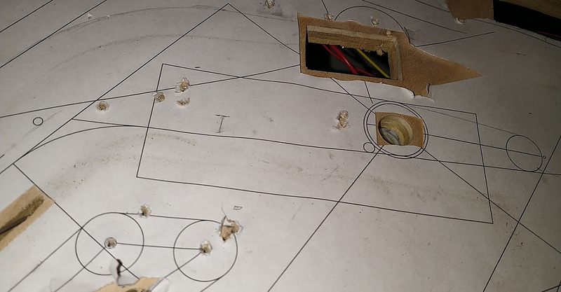
Installed the upper magnet. Needed to cut a 3" hole to fit it, but luckily that just barely left holes for the surrounding stuff that was mounted there. Right below the nearby target you can see one hole where one end of the ball guide goes, which I'm half certain is going to rip apart at some point since there's so little wood left there. Tried to design the mount to hold the magnet slightly below the surface so it won't scratch the plastic, but not sure how that'll work when the magnet is active... maybe I should cut a circle of plastic to 'float' in between them or something? I feel like overall I don't want it to be too much lower, or it may stretch the plastic or something
Cross posted from the original Pinside thread, this is one of many posts regarding my third homebrew pinball machine, creatively nicknamed 'P3'
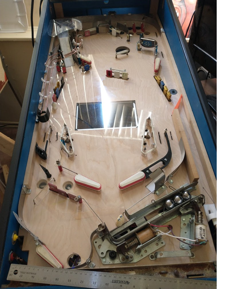
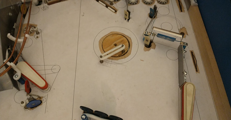
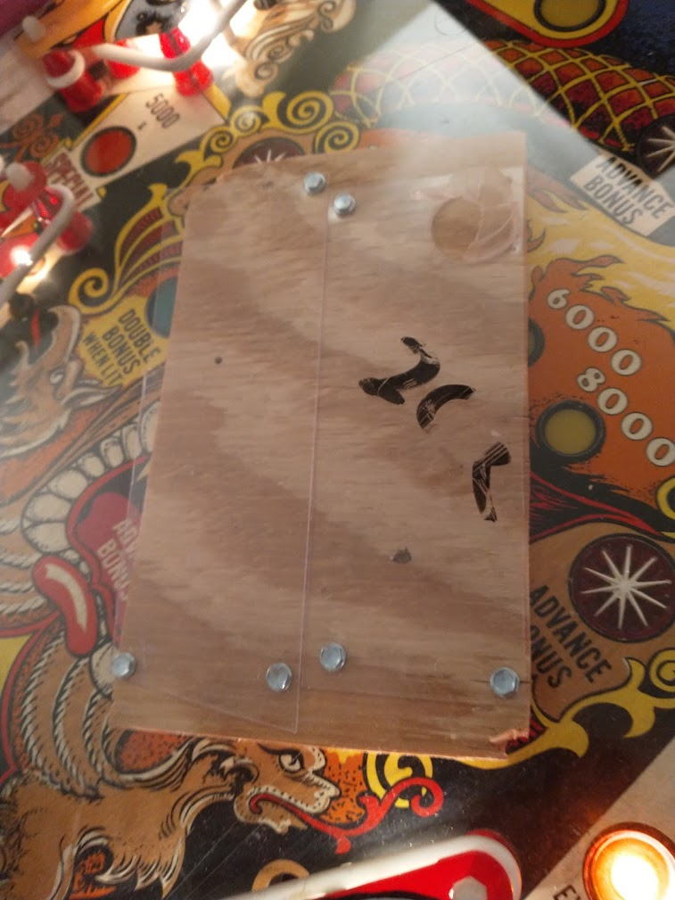
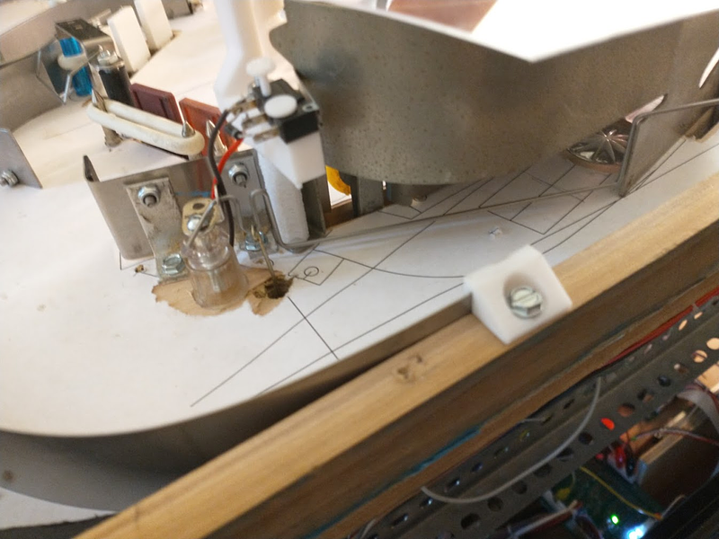
After a lot of careful measuring, it's time.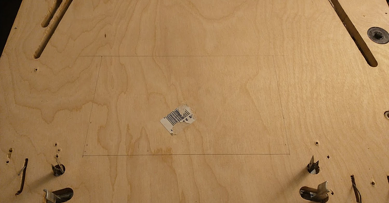
The fit I'm going for is very tight. I'm about 2mm from one of the drop target mounting points, and I'm going to need to relocate one of the slingshot switches slightly, move a fuse block, and make a custom mount for the magna-save, but, it should work.
Printed this magnet bracket, and cut a small stick of 3/4" iron for the core (I think this is the right metal...)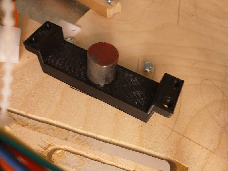
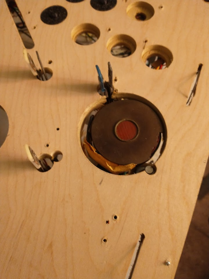
20 agonizing minutes later, I have a hole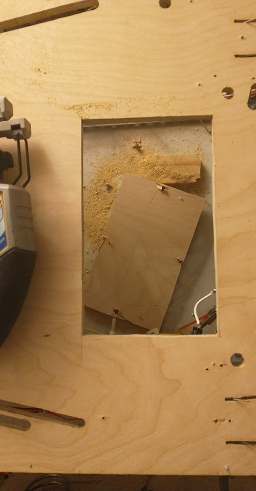
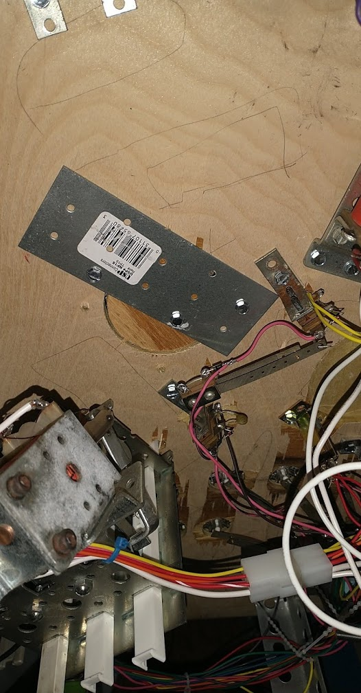
It fits! Barely. You can see the penciled outline of the drop bank on the bottom right, and the currently floating fuse block on the bottom left. I had some room to the top (left side of the playfield) I could have moved it to if necessary, but I wanted to keep it centered between the slings/flippers if possible 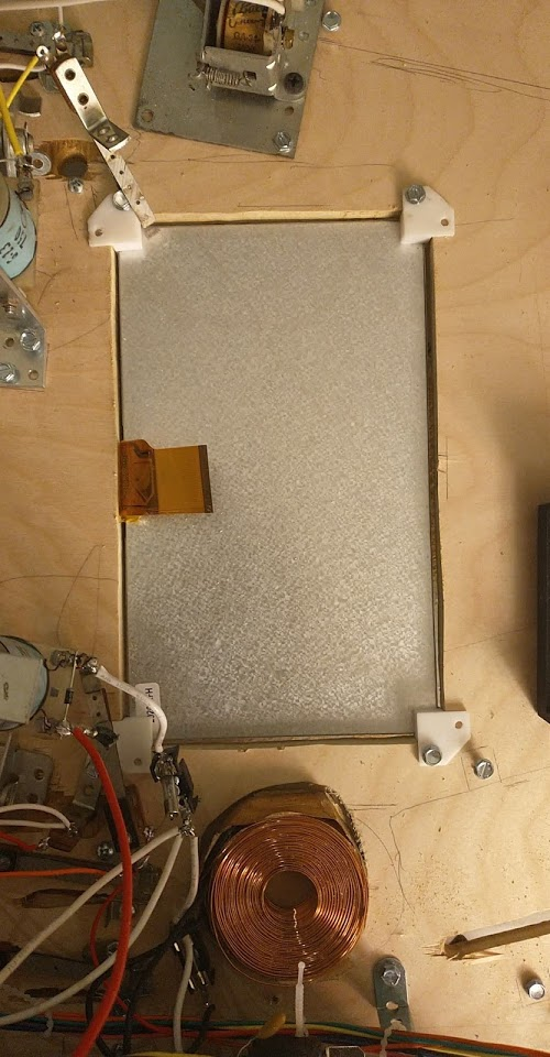
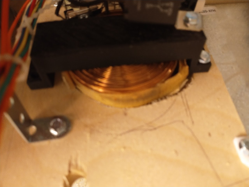
I then mount the control board very professionally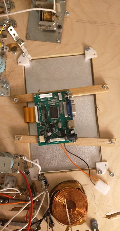 , and hook it up. Success!
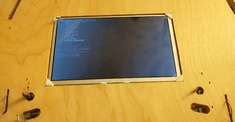
Lets get a game running... 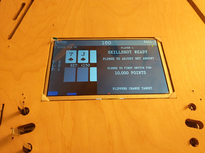
The viewing angles aren't the best but I think it should be okay. Will have to wait until I get it in the game for that though. The supports are a bit too thick and stick out of the playfield, so I'll need to space those or something. Not sure how I messed that up, thought I specifically made them slightly short :/
Cross posted from the original Pinside thread, this is one of many posts regarding my third homebrew pinball machine, creatively nicknamed 'P3'
Reassembled and dropped it in the cab again for more testing. 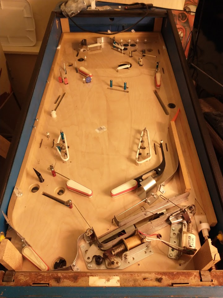
Everything seemed to work fine. No mechs were sticking, no raising of the plastic anywhere. I left it sitting for a while with the transformer+electronics on in case that would trap any heat underneath, but nothing happened. I'm still quite suspicious, but I can't really think of any more testing I can do at this point, and the playfield does look so nice and shiny....
So I took the playfield back out, and disassembled the whole thing again. I'm getting very fast at this, but it's still a pain. One thing I'd try differently next time is the side rails. Currently they're under the plastic, but I think it'd be fine to have the plastic 1mm away from them. This'd save at least a quarter of all the screws I need to remove when taking the plastic off, and prevent the playfield from having time to sag while the rails are removed. Within a few hours of removing them there's a noticeable 1/4" dip in the middle of the playfield, which is more than I'd have expected, especially with all the drop target banks already removed... I assume my playfield wood just isn't as sturdy as what manufacturers use, but nothing I can do about that ![]()
With the plastic removed and everything stripped off, I have some updates to do that I've been putting off:
- the right controlled gate for the top lanes needs to be moved about 1/2" to the left to prevent ball hangups
- the right-most upper lane needs a new rollover drilled in line with the others, since previously it only had a 'bottom' row switch
- need to add lane guides to the upper lanes so the ball doesn't fall the wrong way
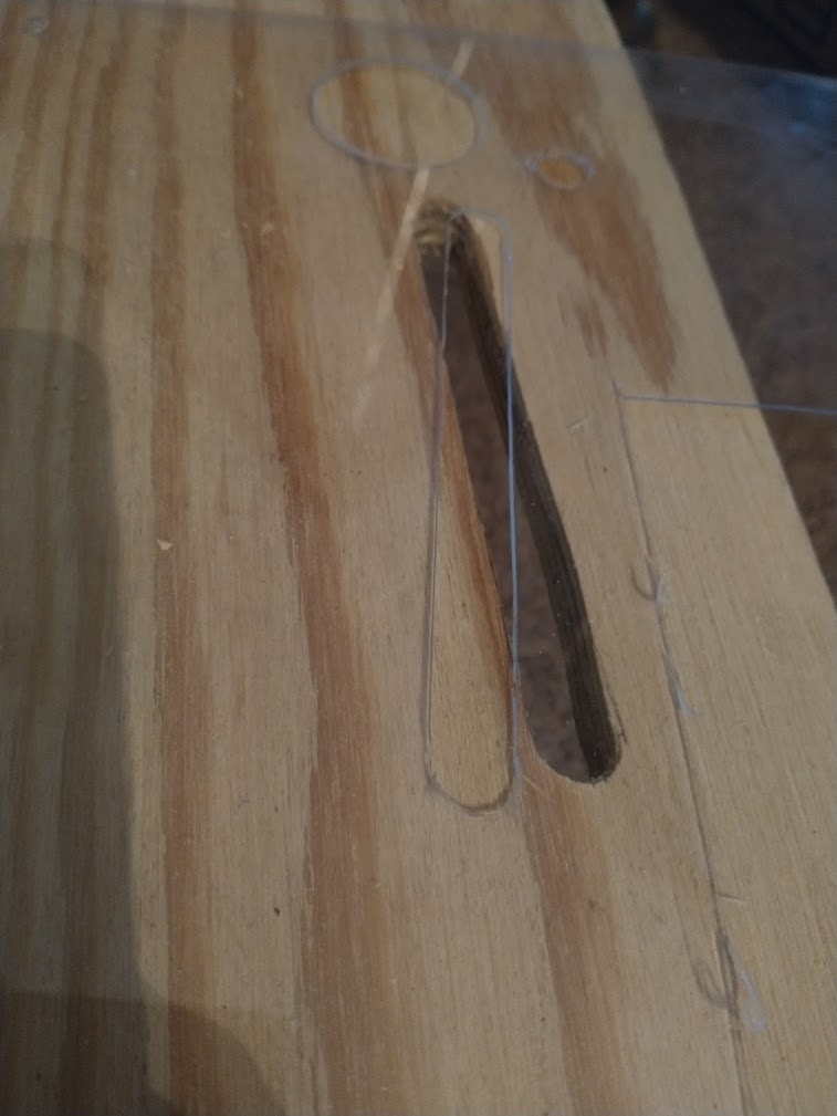
- the target under the upper left flipper needs some tweaking. The hole isn't big enough to fit it through right now, so I need to extend it, and I want to reposition the guide wire below it to give a better feed
- I've removed the upper left target (it was sort of under the ramp above the upper left flipper) since it can't be hit due to the pop bumper being replaced with a rubber (it wasn't really hittable before either), so now I can make a new guide going from the upper eject hole to the upper left flipper that doesn't have a gap in it for the target, which will hopefully improve that feed.
- widen a few holes and slots slightly since some mechs would occasionally bind a bit on the edges
Once that's out of the way, I'll move on to the fun part: cutting a 10" hole in the middle of the playfield for the LCD screen. No chances to mess up horribly here, nope... ![]()
And then I can cut another 2.5" hole for the upper magnet and finally get that installed again!
Cross posted from the original Pinside thread, this is one of many posts regarding my third homebrew pinball machine, creatively nicknamed 'P3'
No noticeable change in the plastic after sitting all day with the lights on it, so time to dig in. I started by just making all the holes for posts, guides, etc.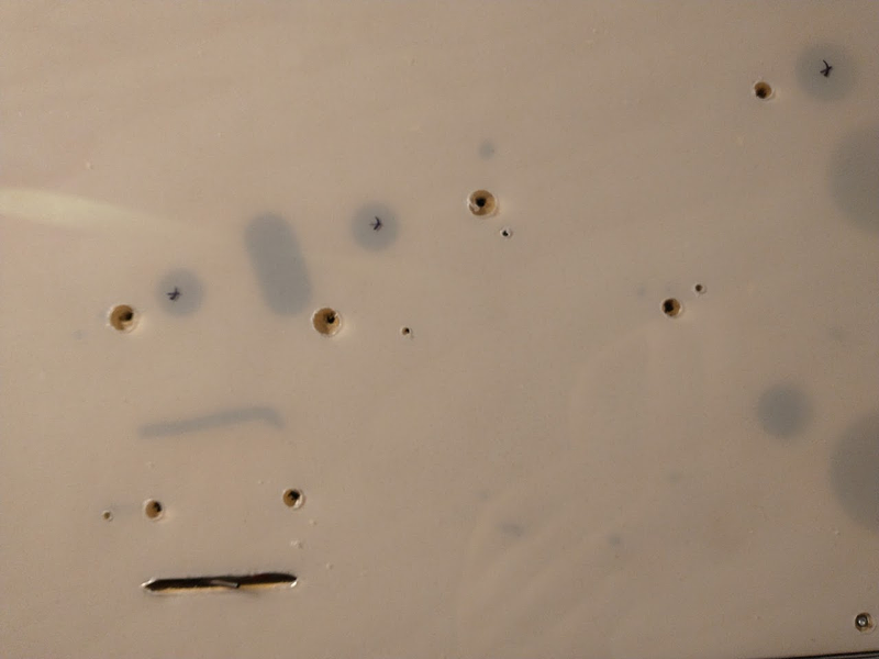
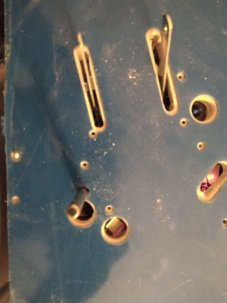
I've gotten pretty good at making clean holes, at least for smaller sizes, but for some reason they never seem to center well. Some I went to a bigger size, others I manually elongated by running the drill against one edge. 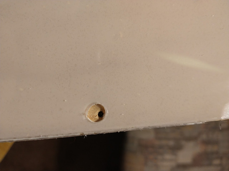
Luckily, with a new blade, making the slots and other straight lines isn't too big an issue. I score each side 3-5 times, then use a hammer to punch it out, and I get pretty clean lines (as long as I get the corners right)
Bigger holes cause issues. Once you get to about half an inch (or even 3/8 sometimes) the bits start to chew up the plastic. Depending on how bad it is I can sometimes clean it up with a blade but it's never perfect. I wish I had a better way to do these, but no method I tried (drill, forstner bit, spade bit, etc) was perfect. It'll be fine for a whitewood, but I think I'll definitely need to get a better one of these machine cut at some point if it all works out.
I'm finally at a point where I have most stuff cut out, enough to reassemble and playtest the game to see how everything works. I've skipped some of the guides, the drop target banks (since they're removed right now anyway), etc.
Cross posted from the original Pinside thread, this is one of many posts regarding my third homebrew pinball machine, creatively nicknamed 'P3'
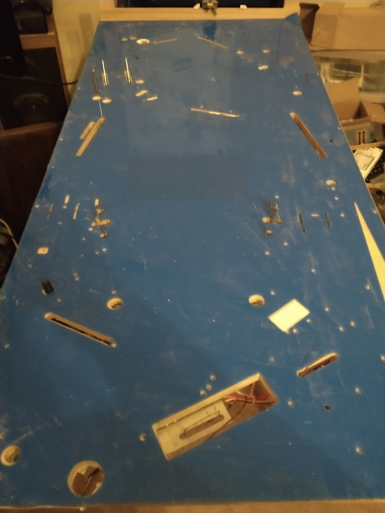
Using my flatbed scanner, I scanned the whole playfield in, since this is probably my only chance to access it completely flat 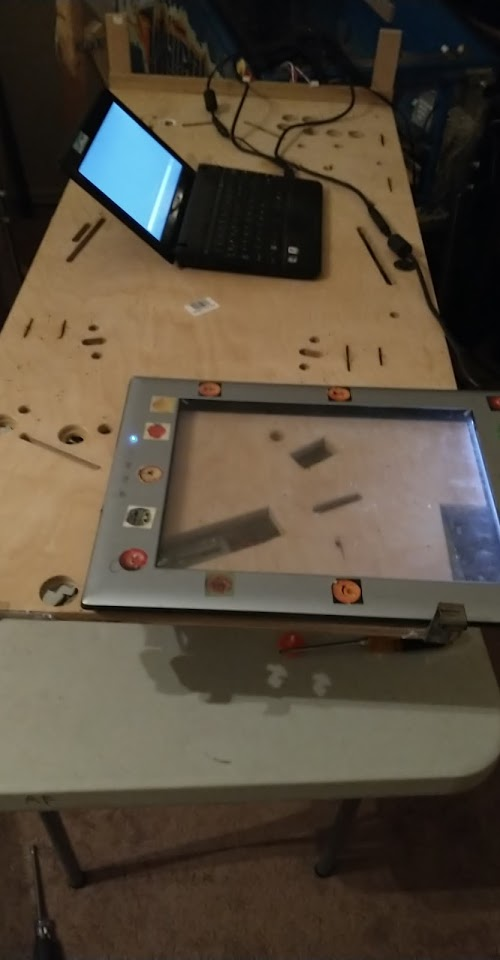
I'm hoping that I can stitch these together and use them to update my CAD drawing to match the hand-changes I made when assembling, though I've heard mixed results about how accurate this can be...

Then I put down my sheet of plastic, which I think is 1/32 lexan, and started marking holes for posts.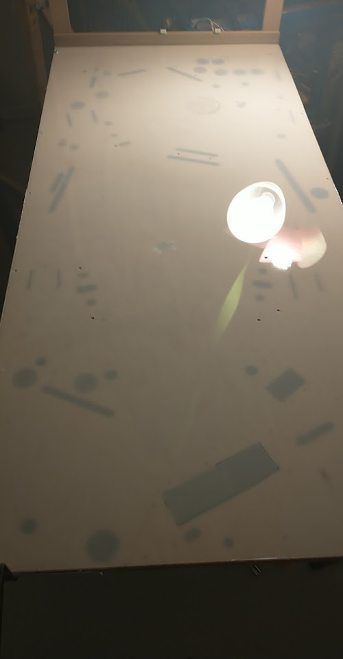
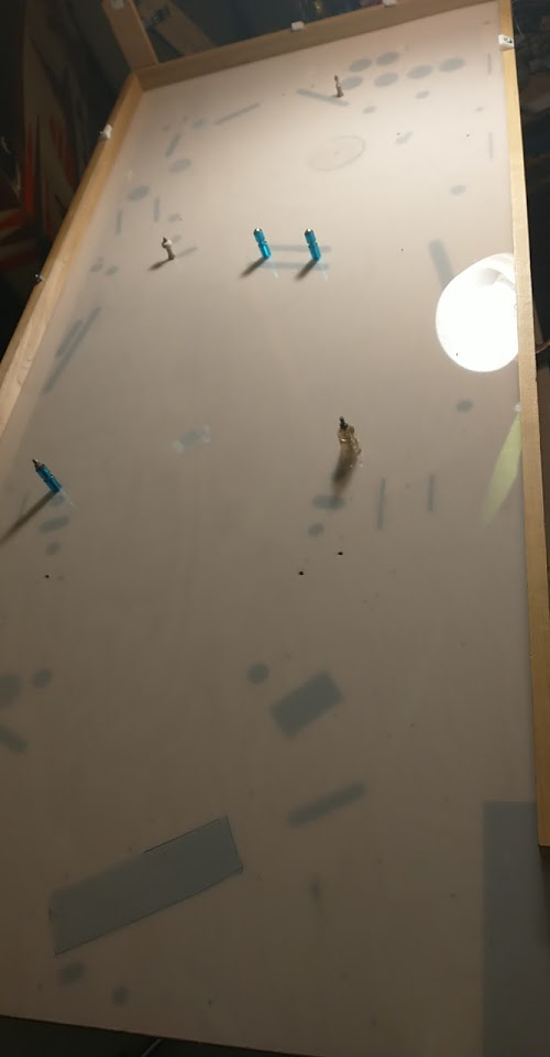
The main worry with this plastic is whether it'll bubble and expand, separating from the wood, which I've seen happen when trying to make playfield protectors. This is a bit thicker though, and lexan, not PET-G; I'm hoping one of those two factors will fix that issue. To test it, the best thing I could come up with is just to heat it up for a long period of time, so I set it up with a bunch of incandescent lamps pointing right at it, for lack of any better options
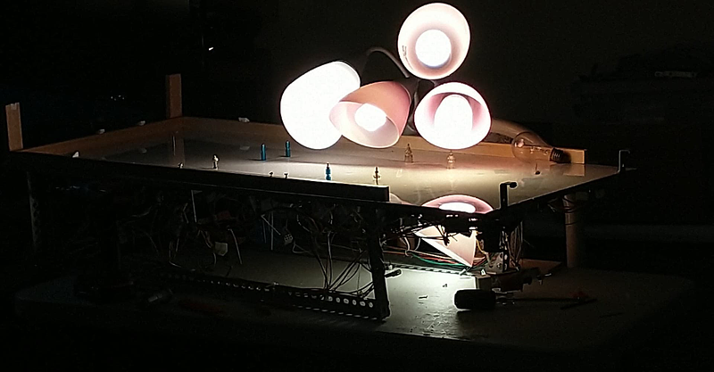
I'll leave this on all day, and see if the plastic rises up anywhere. If not, I'll proceed with cutting the rest of the holes+slots, and reassemble the game for further testing. Not sure if I'll also cut the hole for the screen at this point, or play it some with the protector first before going 'all in' and cutting a 10" hole in the playfield.
Cross posted from the original Pinside thread, this is one of many posts regarding my third homebrew pinball machine, creatively nicknamed 'P3'
Game is getting increasingly hard to play due to the lack of a screen, so I decided it was time to bite the bullet and try installing the plastic sheet, which means I need to strip the whole playfield. Took it out of the cab for the first time in a while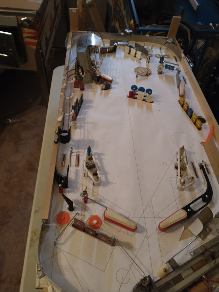
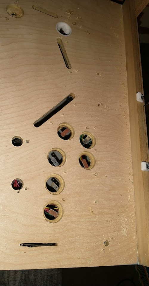
In some places, I'm glad that past-me thought ahead and installed connectors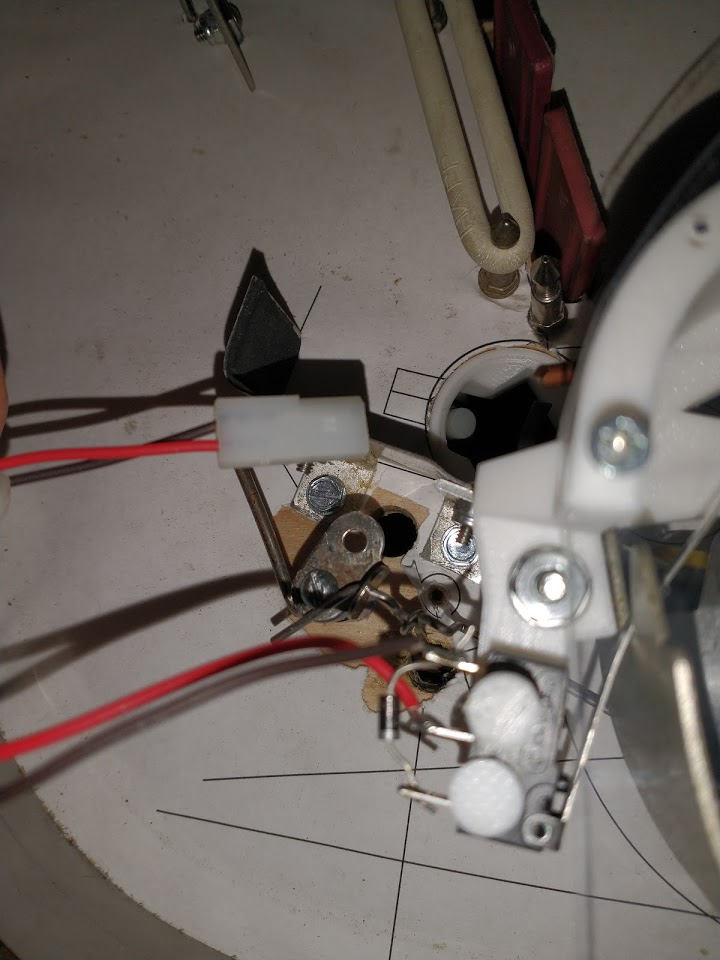
In other places, like the wires going to the trough mechs, I wasn't that smart, so I ended up cutting the wires, and I'll install a connector later. A few mechs I left hanging, since I didn't think to put connectors on them, and now they're wired in such a way that I can't easily add them.
Tear down went pretty quick and painless. There's not that much on top of the playfield, and all the drops have connectors so they're quick to remove.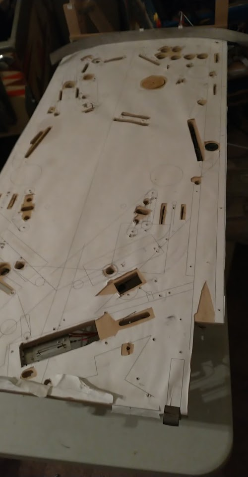
The biggest pain was all the standups. They didn't get connectors either since they're so scattered, and some of them barely fit through the playfield. In a few cases I actually assembled them through the playfield to begin with, so I needed to disassemble the target again to get it out.
The paper has held up pretty well to being played on over and over.
When I first installed it I worried that the ball would rip it up when I started flipping but there's no tears at all, even in high traffic places.
I moved all the playfield components to a spare sheet of cardboard to keep track of them: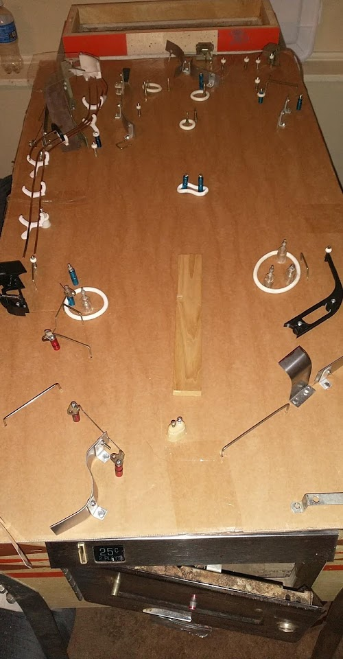
I wasn't very consistent about screws, posts, etc when assembling, and in some cases I even had to do stuff like grinding down plastic posts to make them shorter, so you really can't mix and match anything, and keeping it all straight like this is really important.
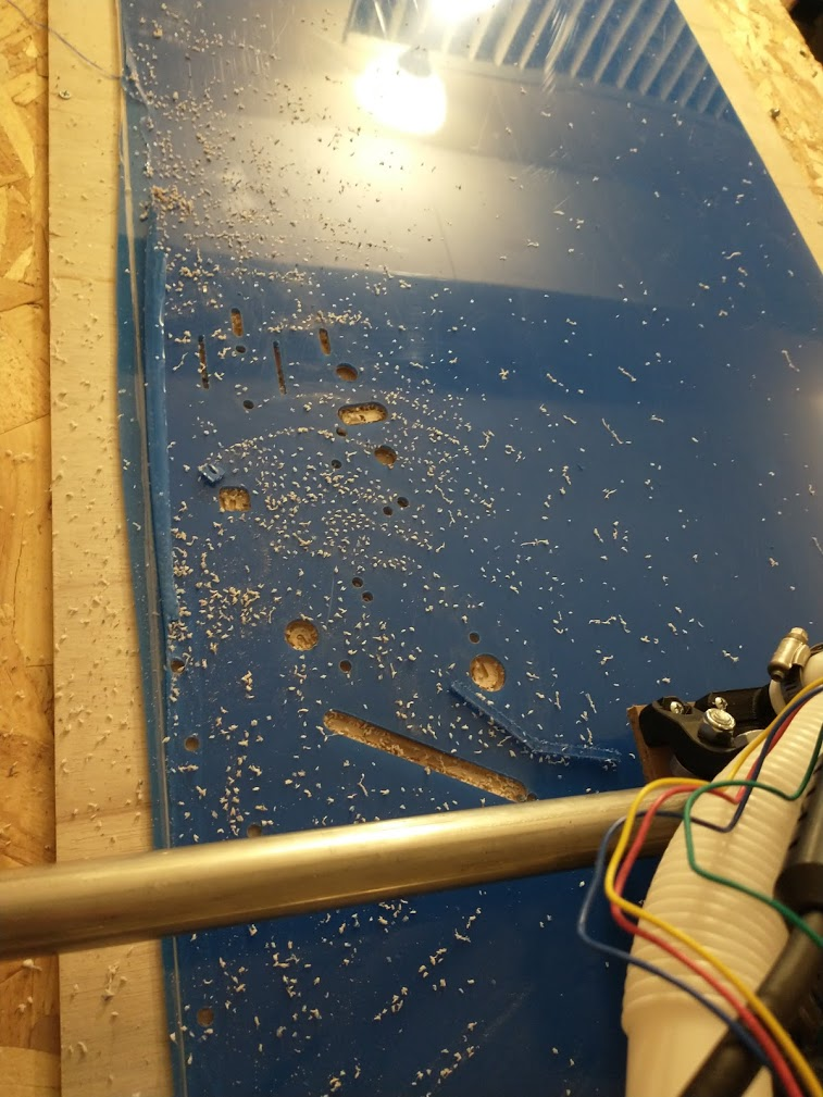
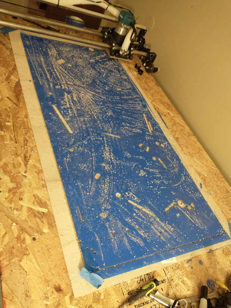
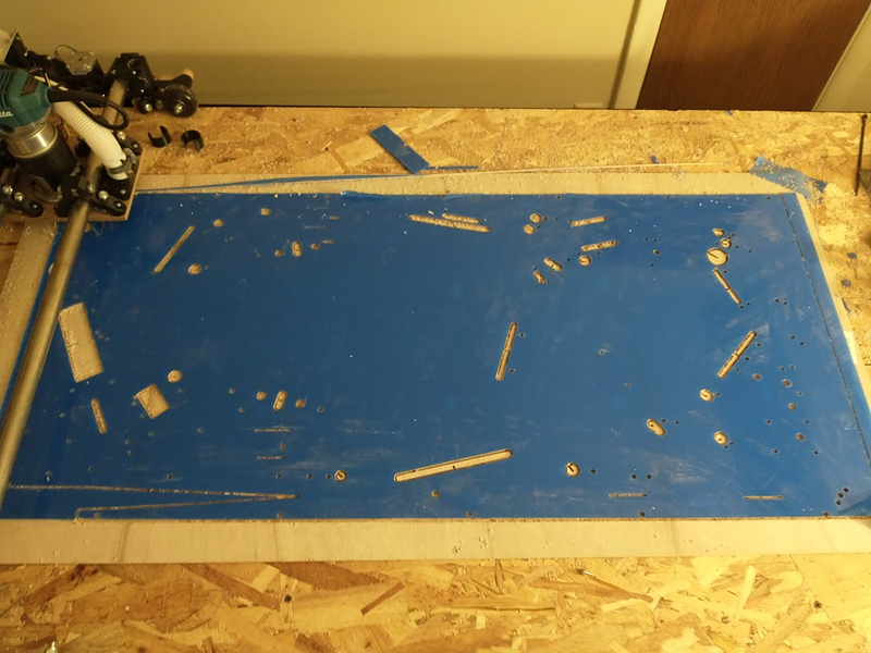
Taking off the paper reveals about what I'd expected: a ton of trapped sawdust everywhere. It's been messing with the ball and getting it stuck in places it seemingly shouldn't
It also reveals something I hadn't anticipated; the wood around every screw is slightly ripped up and standing above the playfield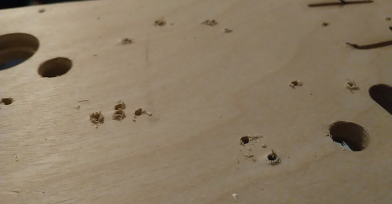
I'm not sure if this is just normal, or if it's caused by me screwing everything in without drilling pilot holes. Luckily these sanded down easily without affecting the finish of the wood at all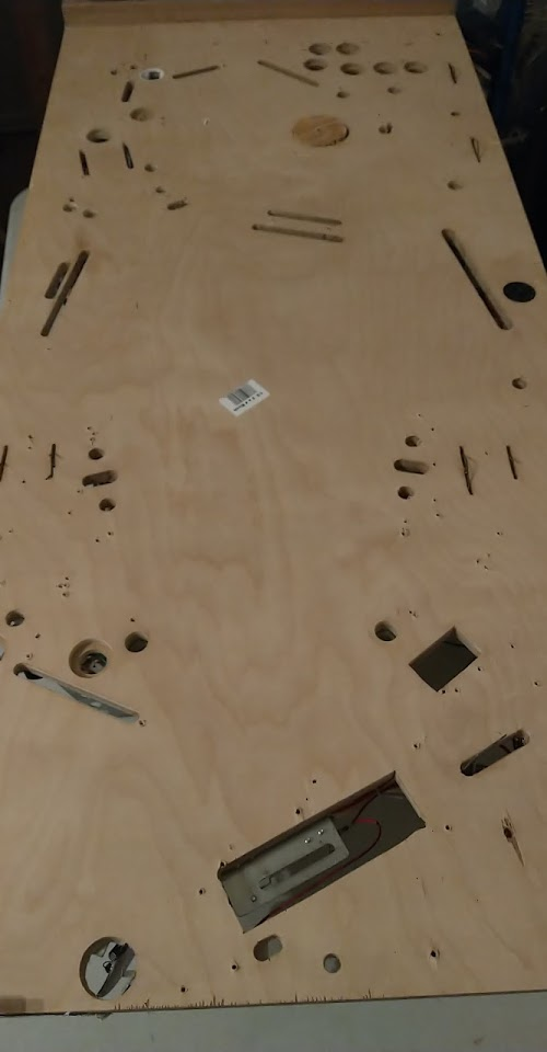
With the playfield all torn down, next I'll need to start cutting the plastic
Cross posted from the original Pinside thread, this is one of many posts regarding my third homebrew pinball machine, creatively nicknamed 'P3'
Installed a tilt bob, which had to go on the right side due to how I'd routed the wiring, etc. Even in this position I'm still going to need to trim the rod some to keep it from catching on stuff. Plus I need to earplug it! 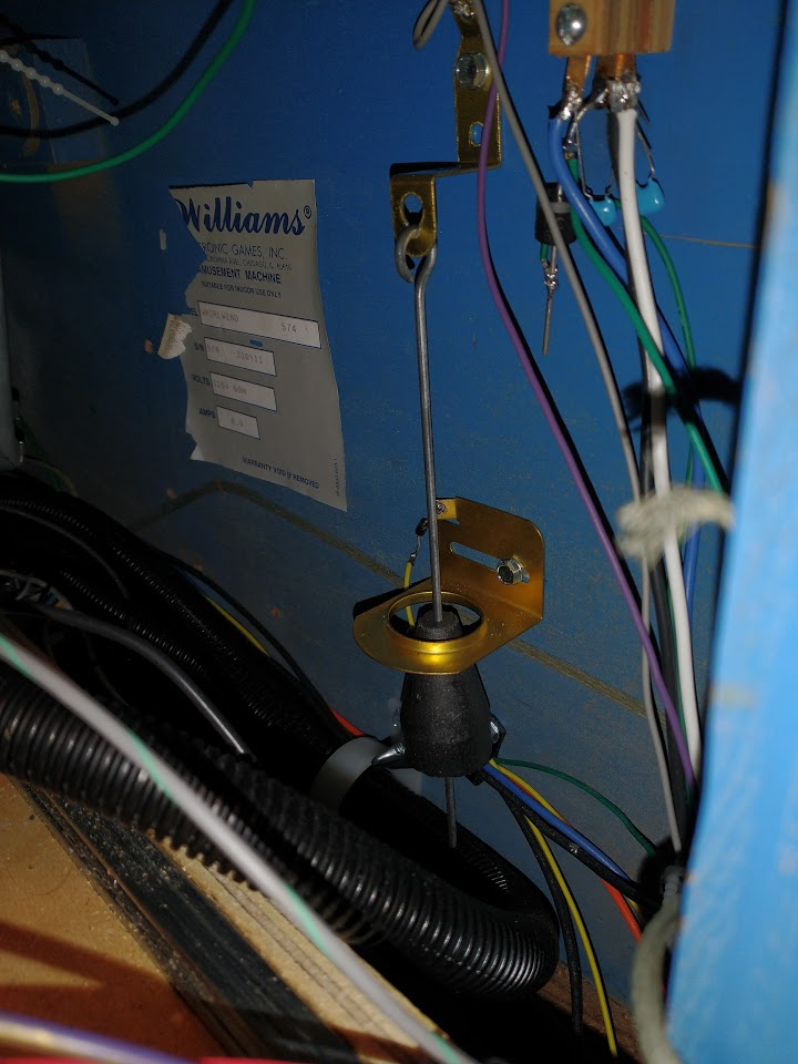
With that installed, I realized I still had no way to kill power to the flippers, so I installed some relays too. Now the tilt works properly in game, and the flippers also aren't energized when there isn't an active game. 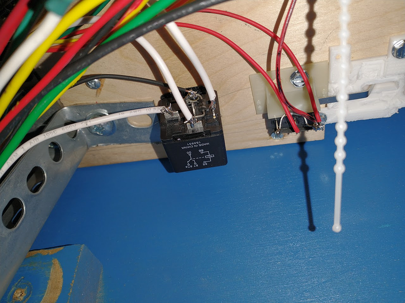
While opening the game to check on something, I noticed I had four pinballs piled in the front left corner of my cabinet. Occasionally, balls hit by the right outlane saver will airball over the lower left flipper/guide and fall down in there, and rather than grasping around for them I just grab another ball ![]()
So I set up an airball catcher, made from scrap lexan and attached to the existing ball guide
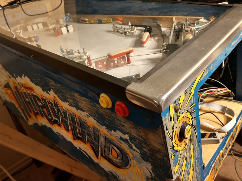
In order to get the height right, I also had to put the glass back in, which was a problem since I didn't have any siderails. I dug a pair of stern side rails (from replacing with lollipop rails) out of my spare parts, and they seem to fit the williams cabinet fine. Eventually I'd like to get proper williams rails on there, but I need to get the secondary holes for the extra flipper buttons, so that's been on the backburner. Since the stern rails are narrower, they fit above the buttons fine.
My lockdown bar is also still covered in rust, so I grabbed one from my whirlwind for now, and for the first time actually had the game assembled with glass+lockdown bar. It's surprising how much of a difference this makes. The game feels much more like a 'real' game. A lot of the noise gets quieted down, which also makes the gameplay feel smoother. A big improvement, although I still need to get a coin door skin somewhere...
With the mechanisms quieted by the glass however, it becomes much more obvious that I don't have any sound effects! I think this is going to be a big focus soon; I need to start finding (or recording) sound effects and callouts for everything. I'm not really sure how I want it to sound either. Most card themed pinball machines are EMs, and the solid state ones fall into that weird early 80s state where the only sound effects that could be generated were laser blasts and explosions (Eight Ball Deluxe always stood out to me for this). By the time sound designers were free to use any sound effects they wanted, poker themes weren't really popular. I think the only two games that'd fit that category are High Roller Casino and World Poker Tour. For better or worse, the sounds on those have never really stood out to me, to the point where I can't actually remember what they sound like to use as a reference. For a while I was tempted to stick a chime box in this game and call it done, but I'd like to try to get some actual sound effects in.
For now, I think I'm going to try to make all the sound effects be related to actual poker. Chips clinking, cards being shuffled, etc. Not a ton to work with but maybe it'll be enough. Not sure how that'll feel as a pinball game either though....
Cross posted from the original Pinside thread, this is one of many posts regarding my third homebrew pinball machine, creatively nicknamed 'P3'
After more playtesting, I decided that it was too hard to catch the ball. With a game where not hitting the wrong things can be as important as hitting the right things, players need to be able to get some control. Even I was having trouble with this, and would often have the ball roll off the end of the flipper while trying to catch it, which I think is partly due to how steep my flippers are (at rest), and thus how shallow they are when raised.
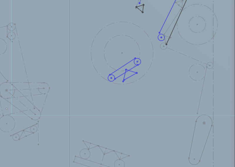
When I originally designed the game I tried to copy the layout of my Alien Star, but I messed up somehow, and part of that was that I put in my flippers too steep. A while ago I picked up a spare gottlieb inlane guide, so I stuck this in my printer and took a scan: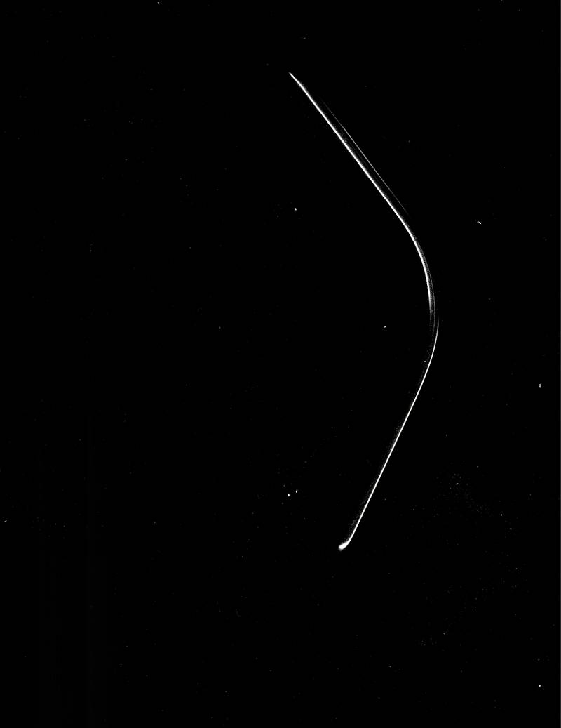
measuring that picture, I got an angle of 119 degrees (probably 120 in reality since that's a nice number...), while my layout was 126 degrees (fun fact, williams inlane guides are 125, so I somehow mistakenly made williams inlanes...). So I made a new inlane guide with a 120 degree angle:https://cad.onshape.com/documents/cf8933508c54fdc1d2e1cbec/w/8de46f8a59b2e2a9657a1015/e/ce2603cfd473c1490421177c
Installing it on the playfield made it look way more dramatic than it was, with the giant gap between it and the slingshot:
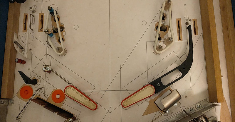
But the actual difference in the flippers was pretty reasonable: 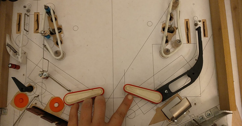
So I went ahead and adjusted the left side as well, and moved the slingshot down to compensate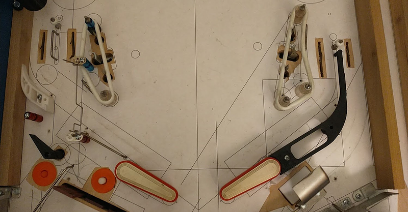
You can see from the old lines and holes how much stuff moved... I'm ending up with a lot of holes in my playfield! When I try to make the plastic for this, I'm going to have to be careful to note which holes are 'current' so I don't use the wrong ones when reassembling.
Cross posted from the original Pinside thread, this is one of many posts regarding my third homebrew pinball machine, creatively nicknamed 'P3'
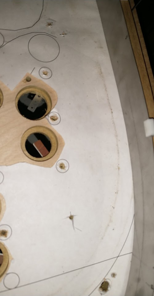
For the second aspect, I wanted to see whether the shot behind the pop bumper could be made if you removed the pop bumper. So I took out the pop bumper: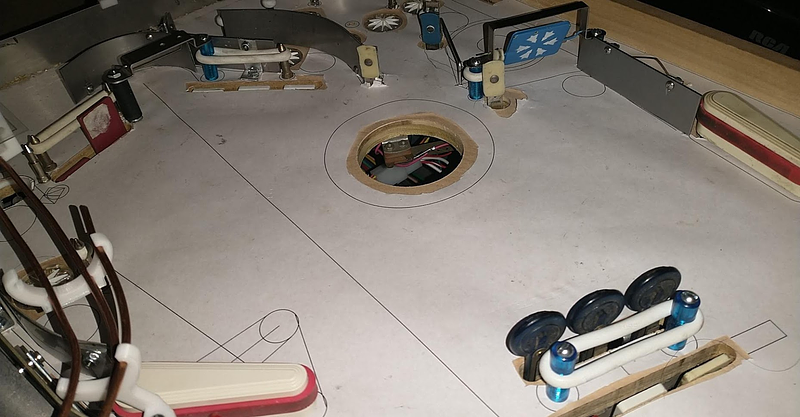
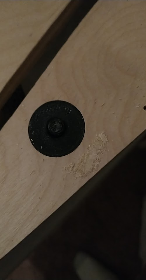
Gobble hole? No, I need to fill it. What do I fill it with? Well, lets just cut another hole with the hole saw and save the piece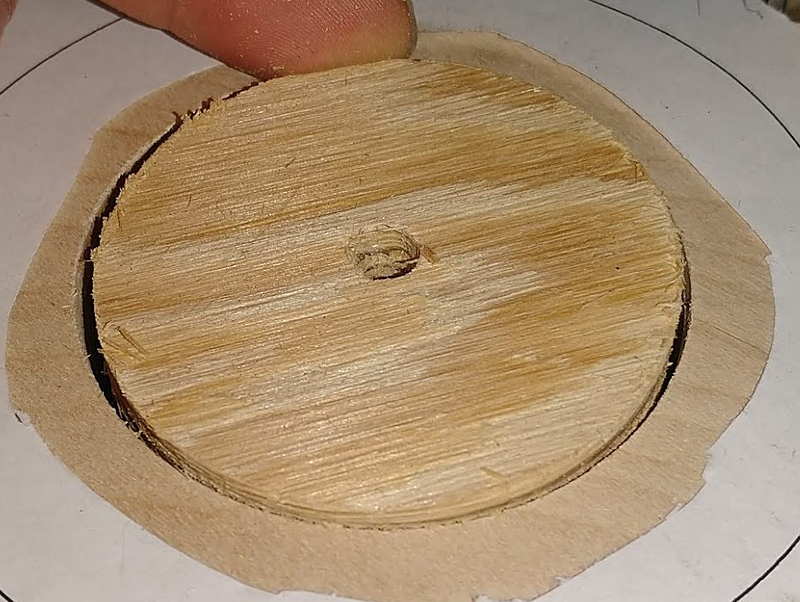
Not a perfect fit, but for testing it works better than expected.
Now... Can you shoot into that area to the right of the back lane?
No problem!
Originally I was going to consider redesigning the lanes area to add another 'shot' here if this angle worked, but I realize there's already a handy blue target right there, that can no longer be hit by the pop bumper, so I don't really need to design any new shots. Just add an arrow insert pointing at that target and make it a jackpot or something, and it goes from 'least useful target in the game' to 'major shot'. Considering the amount of work necessary to redo this area to use two shots instead, I'm inclined to just go with the four lanes from the previous approach and this 'shot' here.
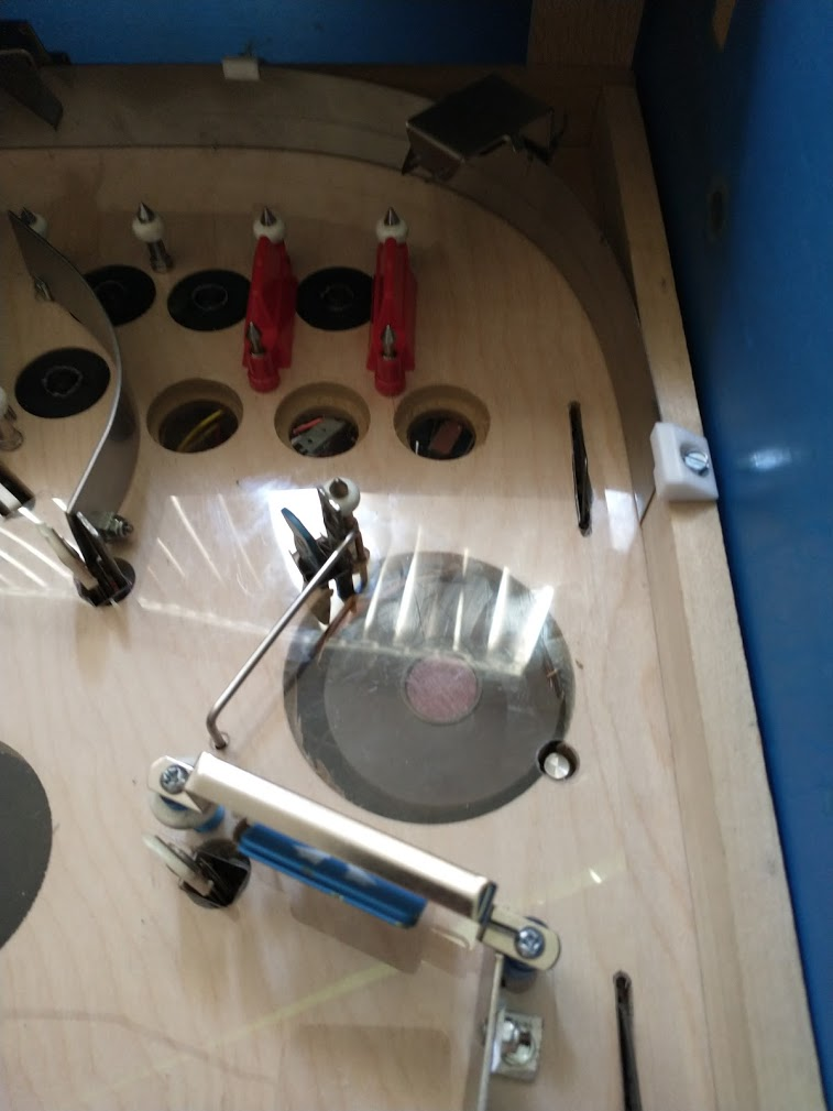
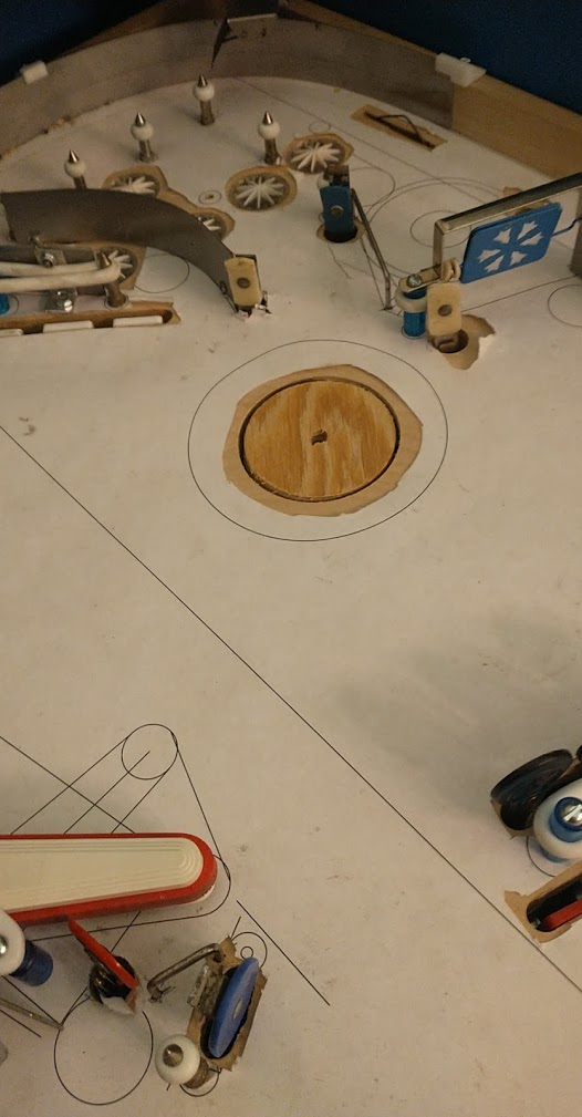
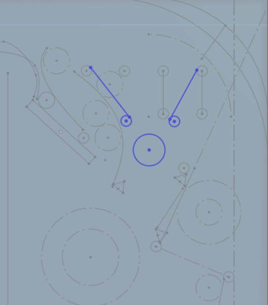
Now for the last bit, should I put something where the pop bumper was? I did a bunch of test runs, dropping the ball from each of the upper lanes, rolling it down the metal guide, shooting it from the upper right flipper, to see exactly where the ball traveled, what angle it was going at, etc, and then took a deep breath and installed two posts.
This is another case where I hate trying to place stuff, since getting these two posts positioned at the proper location and angle to get the bounce I want could take a lot of trial and error, leaving my playfield filled with holes, but I don't really have any better ideas on how to approach it. Originally I'd hoped that both ends of the rubber would be located on my disk I installed, so I could just replace it if necessary, but it was clear from my drop tests that at least one end would need to be on the playfield.
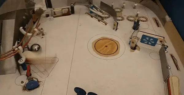
Now... does it work? 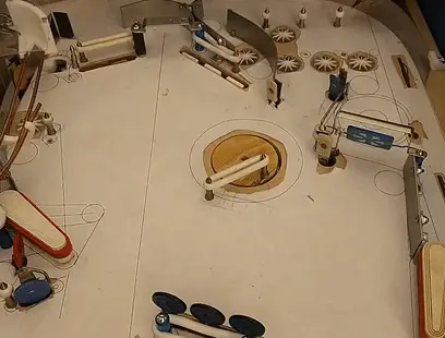
Success! I'd like it to feed a bit higher on the flipper, but proof of concept is working good. I think eventually it'll need be lowered a bit (but not so low that it obstructs the right flipper's path to the upper scoop. A bit of nudge when the ball lands on the rubber should help too. Before fine tuning further I'm going to play the game more and see how this affects other parts of the game, but throwing it around by hand it seems to be working generally how I'd like: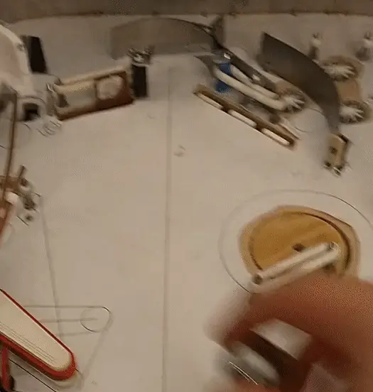
I had also planned to maybe put a standup behind this rubber to be hit by the right flipper, and it looks like from a very early shot you can hit the bottom edge of the rubber, so that does look possible, but I'll wait to do that until I'm sure I like this rubber and its placement. I might also experiment with alternate coil stops/etc on the right flipper to make it shoot at a higher angle.
Cross posted from the original Pinside thread, this is one of many posts regarding my third homebrew pinball machine, creatively nicknamed 'P3'
 Added a post on the upper right of the lanes, and luckily it doesn't seem to affect orbit shots, so I think that converting my two rows into one 4 lane row is doable. Plus, since I still have the switch down below, I don't need to make any further playfield changes for now to work with it. The action is also not too bad. The ball doesn't stay up there long, so you have to lane change fast, but it's not impossible. I feel like the lane change on some games makes it almost too easy.
I do wish the gates were a bit more bouncy though. You only get maybe one bounce off each of them even on a strong shot; I'd like it if the ball bounced back and forth a few times. Not sure if that's something you can do much about though. Maybe I'll play some some foam or springs eventually.
As you can see in the image though, there's one small issue: the right gate is a bit too far to the right, so the ball gets hung up from time to time. I'll need to move it a bit to the left eventually, but for now it doesn't get stuck too often.
Cross posted from the original Pinside thread, this is one of many posts regarding my third homebrew pinball machine, creatively nicknamed 'P3'
Did some testing with the plastic covering... I previously tried to do a full playfield protector on one of my games, but as expected, it warped and raised off the playfield, presumably due to heat expanding/shrinking. However there are many european pins that have plastic playfields and don't have that issue. I'm not sure if that's due to the material (IPDB claims they're plexiglass but I don't know how they tell) or the thickness (I've now gotten confirmation that at least one manufacturer, Interflip, uses 1/4" plastic over their 1/2" plywood).
I cut two strips of plastic, one from the new sheet of lexan I bought for this project and one from the scraps that (I think) are from the previous full protector I made (hard to tell these sheets apart :/ ), and attached them to a piece of plywood, then I stuck it in my Dracula (the only game I have handy that's all incandescent) to 'bake'. After 12 hours, I could see some slight raising on the old material, and minimal/none on the lexan, which is promising at least... I'm not sure exactly what conditions are needed to reproduce the issue though. Is it just heat expanding the plastic? is it air under the plastic heating due to inserts? Presumably it's more noticeable on larger areas with no anchoring, but that's harder to test.
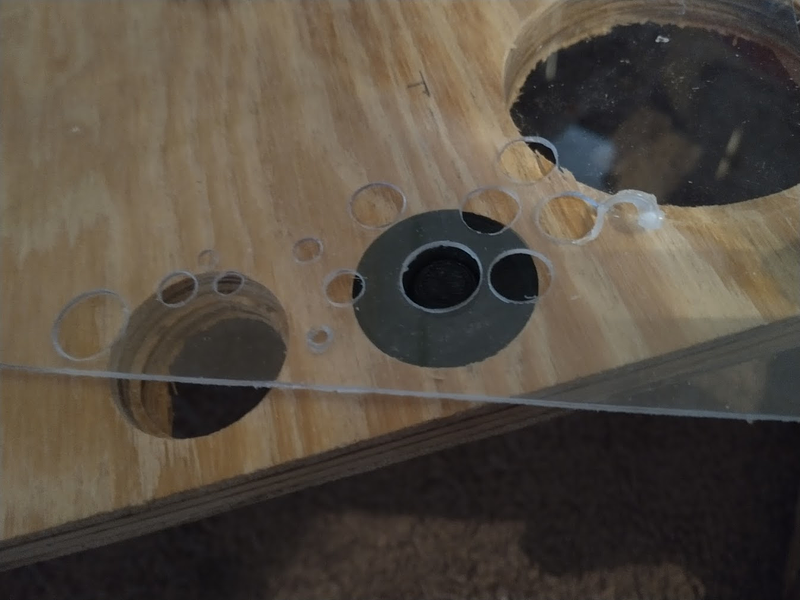
I also did some more practice cutting of my spare sheet of lexan. Trying regular drill bits and forstner bits. The forstner bits seem to leave more of an edge on the holes. Both seem to have some risk of creating weird spirals of plastic (like on the rightmost hole in the picture). Cutting on wood seems to help, I think since the bit can't 'punch through'. I was able to get pretty clean holes with a drill bit at medium speed. Too fast or too slow tended to cause issues. I also need to make sure to hold down the plastic around the bit as much as possible, to keep it from pulling the plastic up.
Experimented with cutting straight lines as well, and found that it's possible to do pretty cleanly with an exacto and ~5-10 passes. Definitely preferable to power tools. Can also be cut with scissors but they're hard to get into the holes since you're not cutting from the edge.
On last annoying thing: apparently the plastic sheet I purchased is 1/32". It's been a while, but I thought I'd requested 1/16 as 3/32 wasn't available, and I felt like that was the most that could be potentially layered on top of a 1/2" playfield without affecting the mechs+etc sticking through. I'll still use the sheet though since I've already got it, and hopefully it works okay. If I run into issues with it flexing or expanding, but everything else is fine, then i'll consider buying another thicker sheet
Cross posted from the original Pinside thread, this is one of many posts regarding my third homebrew pinball machine, creatively nicknamed 'P3'
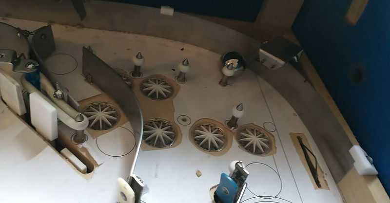
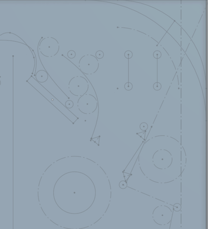
With the gate figured out, I'm almost ready to tear the playfield down and start cutting my lexan covering. There's ones area I'm still not satisfied with though: the upper right area
my original design for this was intended for it to be two offset rows of three lanes, using the shot behind the upper drops as the third upper lane. Like on EMs, you'd shoot up there, bounce around, and try to nudge into the lane you want, then fall down into the pops. But it isn't working out the way I wanted.
1. due to the path of the ball coming through the spinner, I had to remove the mini post I was going to have on the far right of the lower lane, so now balls tend to just roll off to the right instead of going over the rollover
2. there's only one pop bumper, and it's not directly below the lanes. you don't get balls going back up through the lanes much. instead, the ball rolls down to the pop, and gets shot back up to the area below the lanes, and then just falls back down to the pop again. Sometimes this can repeat 5x before the ball works its way around the pop and back into play. Not satisfying.
3. Due to the small size of the divider posts, it's much harder to nudge the ball where you want it than it would be on an older game, which would use 1/2" posts.
4. again, due to the way the ball comes in from the spinner, there's a gap between the rightmost post and the one way gate. When you shoot through the spinner, about 40% of the time, the ball bounces off the left gate and falls perfectly back through this gap, never entering any lane.
5. the lanes are so close to the top of the playfield that there isn't much room for the ball to move around. This also means that the exit of the lane behind the drops doesn't flow well since it just bangs into the top arch. I originally wanted it to shoot around the orbit.
6. because this playfield is longer than an EM, being in a whirlwind cab, the lanes are even farther away from the player, which makes it harder to figure out where the ball is going or nudge appropriately
Part of the small spacing is caused by the lane behind the drops, but I don't want to lose that shot since I want to use it for jackpots during multiball. At a minimum, I need to adjust the playfield somehow so that the ball can't escape the lanes on the right, but I'm considering reevaluating this area further...
A simplification of the lanes?
Basically changing my two sets of three lanes into one set of four. This would solve the gap on the right issue. It should function ok, as long as the rightmost post/divider doesn't interfere with the spinner shot. There'd be no room or time for nudging, so this would have to be just a lane change affair. I'm not sure how much the ball would bounce around up there though, with the upper rail so close to the posts. Would you even have time to read the ball movement and try to change lanes before the ball had fallen into one?
The pop bumper will still feel a bit weird with the ball popping into that dead area repeatedly though. I'd like to move the pop bumper down some, but moving the entire bumper isn't something you can really do once you've cut its hole, so that'd have to wait for another whitewood...
Maybe get rid of the pop bumper completely?
Although I like having a pop bumper (especially one pop bumper, which recalls games like Stars, Meteor, or TNA), I'm not sure it fits this design that well. it tends to make play on the upper playfield very chaotic. If you don't hit the drop you're going for on your first try, you're out of luck because the pop bumper will pop the ball around and take out 2-3 drops before you can get control again, which is half your hand. I'd hoped it be more of a 'danger' off in the corner, but during play the ball tends to hit it any time it's up there.
One thing I originally envisioned for this layout was that the center drops would be angled the other way, allowing you to bump the ball back towards the upper left flipper off them, but the spacing for that didn't work out. Adding a small rubber here might make the play up there more interesting, allowing you to bounce the ball back to the upper flipper. I could put a target on the back of that rubber too, to give the upper right flipper another target to shoot for. It was supposed to be able to hit the target on the upper left, under the ramp, but it turns out the flipper can't hit something that high up, so that target is basically useless.
Instead of lanes, I could try to do something like many williams EMs have?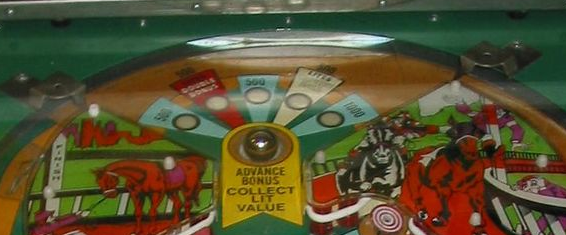
A kickout hole with rubbers on either side to alternate the award. It's a fun area to play in, trying to nudge the ball back and forth to get it to land on the award you want. I'm not sure there's enough room for it, or what the awards could be though.
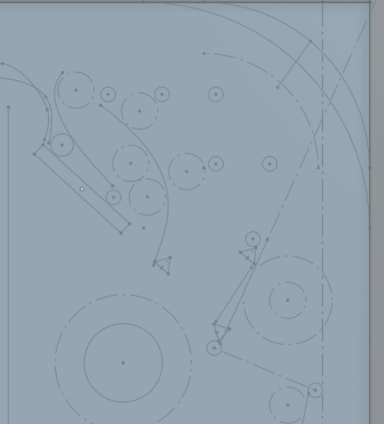
Or maybe something completely different. Get rid of the upper section completely. No more one way gates; the ball always does a complete orbit. Lots of other ways you could take this, but here's one idea I came up with: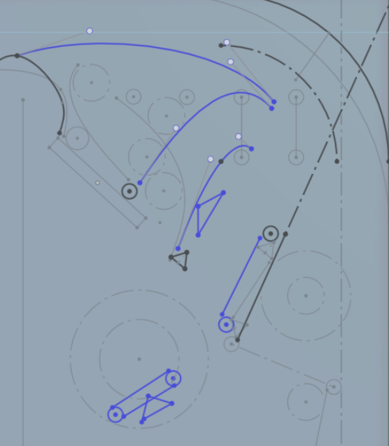
The shot next to the drops is still there, it's just redirected to feed the right orbit cleaner. Hopefully with this the ball could feed down the right to the inlane, or get caught be the magnet to feed the upper right flipper. The area below it could be an extra hard skillshot: plunge just to the beginning of the arch to arc the ball into that lane.
Or maybe that lane is also shootable via upper left flipper? The pop bumper would need to be removed to unblock the shot, but...
Now you have two shots from the upper flipper. One feeds the left inlane to the lower left flipper, one feeds the right lane to the upper or lower right flipper, or shooter lane. I've always thought that was a cool idea, although it makes more sense on a more combo/flow game. Demolition man technically pulls it off, but the side ramp is so hard to shoot compared to the subway that everyone just goes for the subway. With equally easy/hard shots the flipper could act as a 'skill diverter' letting you intelligently set up more combos. Maybe that could still make sense for this game though, as long as the rules set up something for each lower flipper
These last two redesigns look a bit weird on first sketch, but there's a lot of room up there to tweak things and make them shoot smoothly. Having a large empty area like that feels weird to me though... As a designer I like to use up every single square inch of playfield, so having a large empty plastic like that seems like a waste, but maybe it's for the best?
Tomorrow I'm going to pull out the pop bumper and patch in some wood in the hole, and see how the upper area plays like that. Does it shoot better? Can an extra rubber there make the ball bounce back the way I'm thinking? Can the upper left flipper hit that rightmost shot? Can the upper right flipper hit that rubber?
I'll also try placing some more posts in the upper right area, see how far to the upper right I can put stuff without interfering with the spinner shot. I imagine if you get too close to the upper arch the ball is going to hit the post, since it's probably rattling around a bit as it meets the rail...
Thoughts? Any other cool ideas?
Cross posted from the original Pinside thread, this is one of many posts regarding my third homebrew pinball machine, creatively nicknamed 'P3'
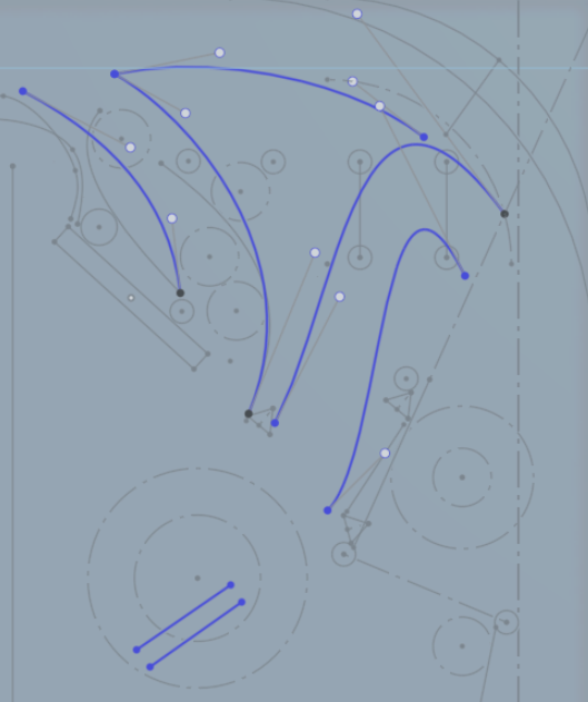
I tried to write some code to make use of the left orbit (under the ramp), and realized I had no good way of detecting shots through there. I had originally placed a rollover under the ramp, and a hanging gate across the exit from the back the ramp. That way, shots that hit the rollover first would count as orbit shots, and if a shot just triggered the gate, I'd know that was the end of a counter-clockwise shot from the spinner as it entered the left lane. The rollover under the ramp also doubles as a way to detect balls that, coming around from the spinner, fall under the ramp instead of going down the left lane, so I can raise the ramp temporarily to let the ball out. Which is good since that happens *a lot*. That should have all been good, but it seems it's possible to shoot under the ramp and not trigger the rollover, probably due to the width of the ramp and the ball bouncing around. So often I was just getting the gate switch, and had no way to tell which direction the ball was going, which was a problem. I also wanted to improve this area to give a cleaner feed to the left lane from the spinner, and prevent balls going under the ramp from the back so often.
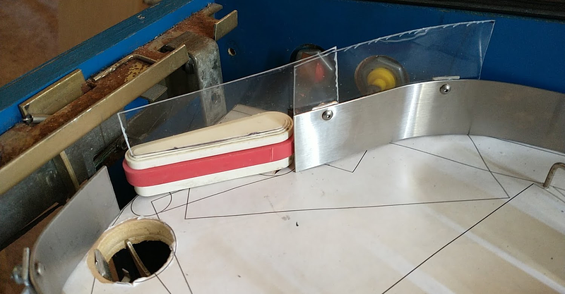
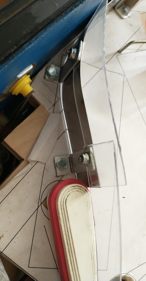
Enter: the longest gate ever
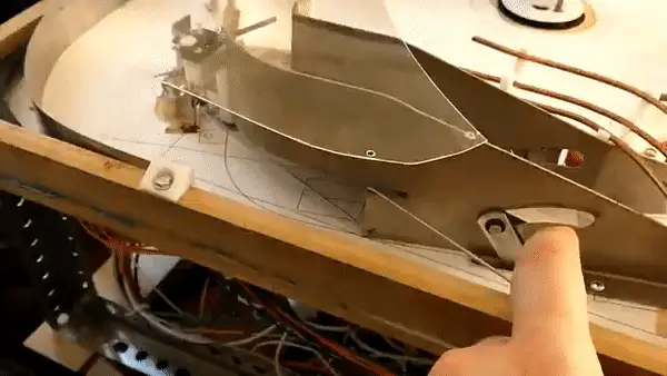
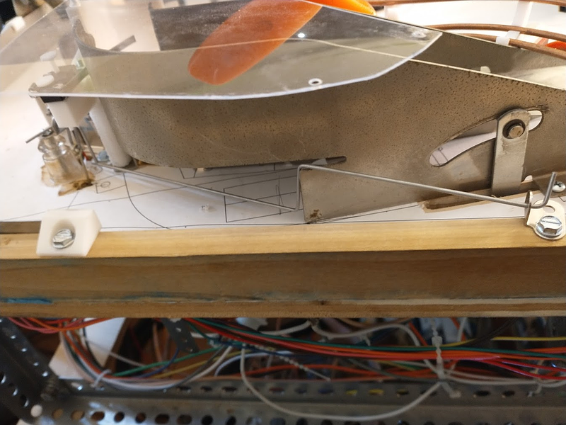
Now it senses balls coming through the left orbit, using the same hanging wire as the previous gate did, and prevents balls from going under the ramp from the back, instead feeding them to the left lane. These little gottlieb L brackets for mounting gates+spinners are a life saver, they allow me to do all kinds of weird things with gates. Just need to make sure they're aligned properly
Cross posted from the original Pinside thread, this is one of many posts regarding my third homebrew pinball machine, creatively nicknamed 'P3'
I realized that the top lanes still did nothing outside of the skillshot, so I decided to add a quick rule that one lane would give you more magna-pulses, but this reminded me that I still didn't have any ability to sense the flippers being pressed. I've been making do so far with using the secondary buttons for stuff like navigating menus, but you can't really use those during gameplay, and I want to add a status report soon since I'm getting to the point where the screen is getting filled up with information.
Since I'm using directly controlled flippers with high voltage contacts, this isn't as simple as it would be with software controlled flippers. I don't want to use switches on the flipper mechs like early games did since that seems to have some lag sometimes, and I can't add switches to the buttons since they're already double stacked for staging, so I'll need to do it electronically. Looking at other games, system 11, WPC, and gottlieb system 3 use opto-isolators to sense the HV signal going to the flipper, but I didn't have any on hand and have never used those before, so I tried to come up with a simpler solution.
My thought was, since my flippers are grounded by the cab switches, I should be able to just hook some 3V circuitry in parallel, since ground is the same for both. I put a diode between the chip and the cab switch to prevent the high voltage from going backward, and used a 74367 tristate buffer chip, so I could hook the switch matrix column to the enable to simulate a physical switch. A quick test with a breadboard hooked up to the switch seemed to work, so I assembled this one off board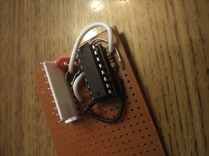
Optimally this would have been part of my MPU board, but I wasn't sure what the circuit would look like at the time, so I left it off. Once it's battle tested I'll probably design a new MPU with the added stuff but for now this'll have to do.
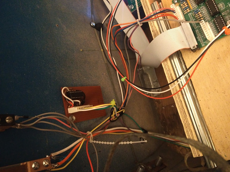
Wired it up and ran into an issue... hitting either flipper button registered both sides. of course, not something I ran into when testing just one side with the breadboard. The signal seems to be traveling backwards into the playfield, through one coil to the HV line, then back through the other coil. I ended up just putting some beefy diodes in line between the flipper coils and the contacts to prevent that.
Also had an issue where the right flipper button (row 1, column 8 ) was also registering as the switch in row 1, column 1. Left button (row 7) was fine. Eventually concluded this was just due to the order I scan the matrix (row 1->8 for each column 1->8 ). I must be scanning it faster than the circuit through the chip can react, so it's still reading as closed for the next column (1 is after 8 ), but corrects itself before it gets to the other rows. Added a tiny delay after finishing the last column to account for that.
