
Custom Bally OS, Pt 3: Lamp Control
Many months later I have picked up a nice Stern Dracula pinball machine, which allowed me to actually go and start testing this code in a game and get working on the I/O support.

Bally has an interesting system for driving their lamps. Unlike Gottlieb (who just had one transistor for each lamp and banks of latches to remember their state) or Williams (who used an 8x8 switch matrix), Bally opted to use 60 individual SCRs. SCRs have an interesting property to them: unlike transistors, which allow current through when there's voltage at their input and then cut it off when the input turns off, SCRs will keep letting current through until the input turns off, and the current drops to zero. This has a cool effect in that, you can hook a lamp up to an SCR, give it a quick pulse on its input, and then just leave it and the lamp will stay on. Of course, you don't want your lamps to stay on forever, so Bally powered all its lamps via raw rectified DC, which follows the same 120Hz sine wave the 110VAC coming from the wall has.
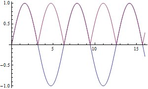
You can see the DC in purple here compared to the AC in blue. Effectively a rectifier just inverts the negative half of the AC signal, which means the DC still looks like an AC wave. Because of this, the power source for the lamps is dropping down to 0VDC 120 times a second, stopping current from flowing through the SCR, allowing the light to turn off. So what Bally does is, 120 times a second, the MPU pulses any lights it wants to be on, and then they stay on until the next 'zero crossing'. As long as the MPU pulses the lamp again right as the SCR turns off, the lamp appears to stay on. If it wants to turn a lamp off, it just doesn't pulse it any more. Pretty nifty, but it also means timing is going to matter a lot here, since there's factors beyond the MPU's control at work.
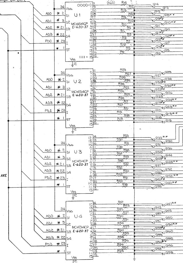
Of course, this complicated system wouldn't be very useful unless you could also pulse all your lamps simply, so Bally hooks up each bank of 15 lamps to a 4 to 16 decoder. This chip has 16 outputs, and turns only one on at a time depending on which 4 bit binary number is sent into it. Unlike Gottlieb, who needed a dedicated output on each chip for every light (limiting them to 4 lights per chip), Bally could use one chip for 16 lights. But I said 15 earlier, right? That's because one of those 16 outputs isn't connected to anything. Since the same data lines that the MPU uses to control the lamp board also go to the displays, they use one output as a 'safe' output to leave the lamp board on while the MPU does other stuff. (The same is done with their solenoid board, which can control 15 solenoids from its decoder).
15 lamps per decoder means we need four decoders to control 60 lamps, and four also is a nice round computery number. All four decoders are hooked up in parallel, so another set of 4 bits, one per decoder, is used to enable/disable each one while all 15 outputs are run through. 4 bits happens to be the size of the 5101 RAM chip on the MPU, so 15 bytes of that RAM will go to storing the state of all the lamps.
With that in mind, I feel like I have a pretty good idea of how to interface with the lamp board:
Each time the lamp voltages crosses zero, the MPU gets an interrupt signal and starts the lamp update sequence
Load up each 'row' of four lamps
Combine this with the 4 bit 'column' address for the decoder
Send them out as one 8 bit byte to the lamp board
'strobe' the decoders to tell them to latch in the data
Repeat for the rest of the rows
Nice, simple code, aided by the four 'data' bits of the lamp board inputs being mapped to the top 4 bits of the MPU PIA's 8 bit output port, which coincidentally matches which four bits of RAM the data is stored in. Almost like they planned all this! Too bad it didn't work. The lamp I wanted to turn on did turn on, but so did another in the same column.
After some thought, I realized that the decoder chips only 'latch' the address. The enable/disable data signal takes effect immediately. So when I sent out the next combined byte containing both the 4 data signals and 4 address signals, the new data for the next row must be affecting the previous row.
So now I had another step. Instead of sending them both out at once, first I'd have to disable all four encoders. Then, I'd send out the new address and latch it in. Finally, I'd enable to encoders again. A bit slower, but much safer than relying on the timing of the two signals to work out. Of course, this also didn't work.
After tearing my hair out for a few days reading and rereading data sheets for the decoder chips, staring at schematics, and scrutinizing my code, I finally discovered that my data sheets were wrong! The part number on the schematic was 14514CP, but my data sheet was for 14514B. Very similar chips, but with one important difference: for the 14514B the way to latch a new address was to drop the latch signal from high to low. That transition was what triggered the latching of new data. With the 14514CP, when the latch pin was high, it was instantly passing the address data through. Dropping the latch pin low just made it stop passing the data and remember whatever it had last. So I rearranged my code to quickly pulse the latch pin high for a few microseconds, instead of leaving it in one state or another, and finally my issues were solved
The code for all this is available on my github, if you want to check it out
blog comments powered by Disqus