
Now for the fun part: my first board!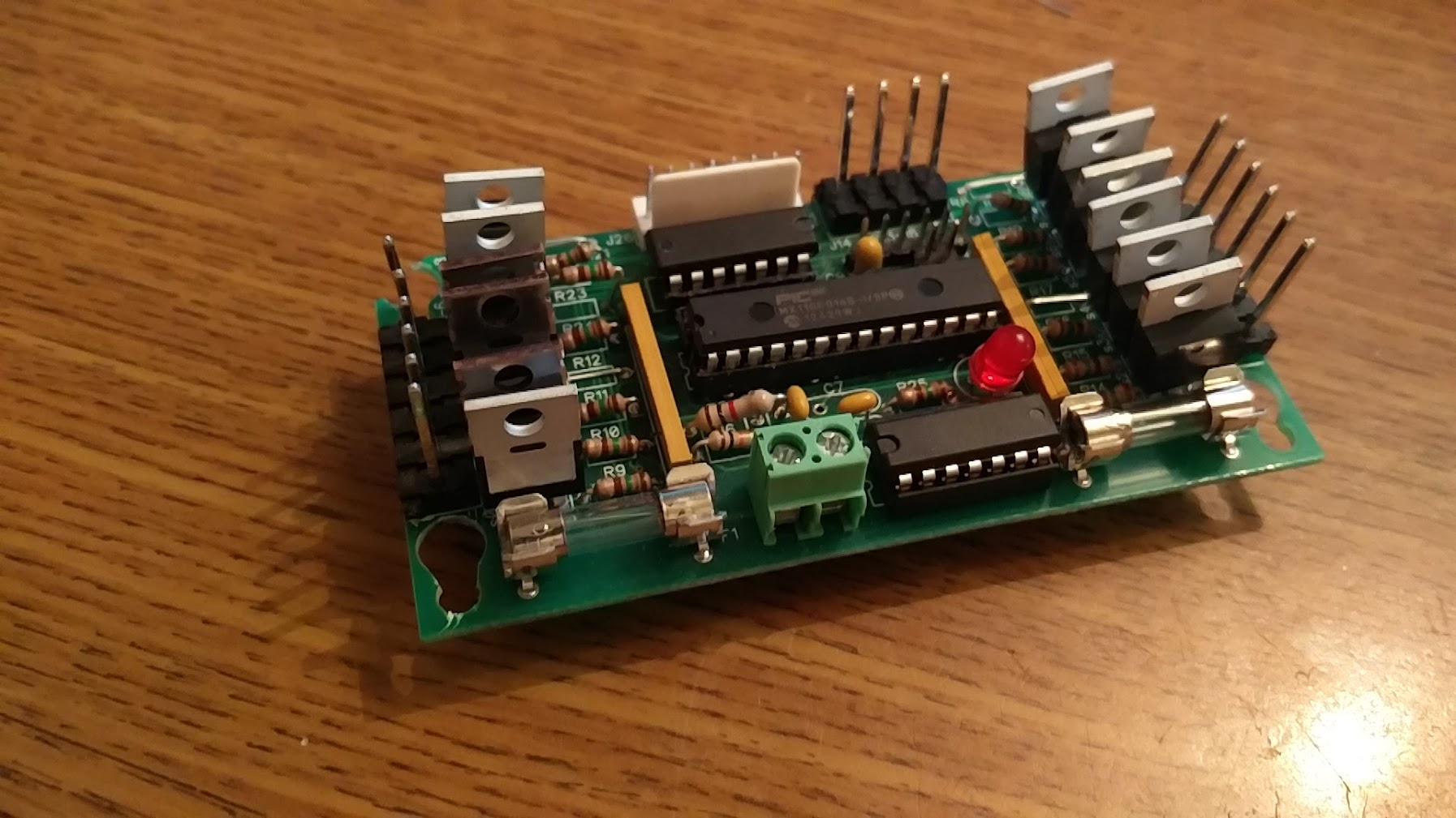
I've been hoping to avoid FAST/PROC for cost reasons, and rolling my own sounded like fun, so I designed these. 2"x4", 16 drivers controlled by their own dedicated processor. 12 'high power' drivers using a step up chip to convert the CPU's 3V signals to 5V, 4 low power drivers for things like relays, which can also be configured as fast react inputs by replacing the mosfet (an IRL540N) with a jumper wire and all controllable via SPI. I'm hoping these can act as psuedo node boards spaced around the playfield to reduce wiring.
From prior experience making a homebrew 5 years ago, I know that direct high current switches can be a pain to deal with due to the arcing and EMI causing board resets, so my goal for this project is to have everything transistor controlled, but for initial testing, I'm going to leave the EOS switches on the flippers wired in.
I installed some low current stagable flipper buttons in the cabinet, wired them up to 3V, and ran a connector up to the playfield through zip ties on the support rails. Mounted my driver board under the trough for now, and hooked it to the lower flipper, and had my first flip! Success!
Well, until I hooked up the second flipper. Then both flippers flipped at once! A bit of troubleshooting narrowed this down. As should have been obvious, don't run your low voltage signals in the same bundle as your high voltage coil wiring! Basically, when I flipped one flipper, the first 3V pulse would go to the board fine, and it would engage that flipper. All the electrons flowing up the harness would create a magnetic field and induce enough current in the flipper button wires to be read as 3V, triggering the other flipper as well. I knew that generally, you want to keep those harnesses separate, but didn't expect to see that so soon, and so reliably.
Luckily, the next day I was at some friends' wedding, with a pinball machine in tow, and I got talking to another guest who was an electrician, who confirmed my issue, and told me that "about 6 inches" should be fine separation for the signals I'm dealing with, as well as the advice to try to cross high and low current at right angles when possible, which doesn't sound too bad. Since all the switches and lights will be close to the playfield anyway, I'm now planning on having two layers of wiring: one high current harness run through the rails, and one lower current one near the playfield. In the mean time for testing, I just run a separate wire down directly, bypassing the harness.
With that 'working', it was time to actually test the shots! Instead of moving the playfield in and out of the cabinet all the time, I found a two foot block of wood whose thickness would result in a 6.5 degree incline if I stuck it under the back end of the support rails, allowing me to play with the playfield sitting on a table next to the cabinet. This revealed that, despite me trying to account for it, my connector from playfield to power supply was too short! I spliced another 2 feet in for now. Lesson learned: always make your connectors way longer than they need to be, and then make them longer.
So I made my first shot, at the spinner, and actually hit it which was surprising considering that I was standing two feet to the left at the cabinet. However, it also illustrated a new issue: the ball didn't even reach the back of the playfield. I took another shot, avoiding the spinner so it couldn't steal any momentum, and was able to reach the top, but the power just wasn't there. It felt like playing a gottlieb EM with AC flippers. I tried playing with the pulse length, etc but nothing helped. To rule out the board, I tried manually grounding the flippers, and they were super strong! So the driver board was causing issues somehow...
I tried taking the CPU out of the equation by controlling the step up chip directly, no different. Tried sending 5V directly to the mosfet, no difference. I looked up the schematics for other games, since most modern games seem to use IRL540s, but couldn't see any difference. I tried driving the mosfet with 12v instead of 5V, since it technically can go that high, and the flipper seemed a bit stronger, but still not close to how it was when grounding it directly. Very confusing. I'm not sure if there's something else with this circuit I'm missing that's causing issues, but I think I eliminated every part of it being an issue. Maybe it's something with driving these very high power flipper coils on 25V (resulting in very high current), vs how modern games all use 50V with weaker coils? I also discovered that Stern node boards have special driver chips designed for mosfets, although they run them at just 6v, so those might be worth a try, but no other manufacturers use anything like that so it doesn't seem likely. The issue only seems apparent with flippers too; my drop target bank resets fine, the outlane saver is nice and strong. Both of those use a weaker coils though.
I'd love to figure out the answer to this, but for now I decide to work around it for testing, so I swap over to high current flipper contacts. I don't mind this too much really, since it's more like how the gottlieb games originally worked, and I love the feel of 80s gottlieb flippers. No need to spend time trying to get CPU controlled flippers working really nicely or anything, just do it old school. I'll have to add some arc suppression to the cabinet and eos switches, but that's not a big hurdle. I'm also gratified to see that my driver board seems to work fine (no resets) even without the arc suppression, so maybe my increased electronics knowledge is helping too.
With the directly controlled flippers, the game is nice and powerful. Perhaps too powerful! On my third shot I break off one of the drop targets on the center 3 bank. The spinner shot works well though, the ball makes it all the way around and comes down the left side. Will need to work on some inlane guides. I wish I had a laser cutter....
All the lower flipper shots seem at least makable. I would have liked the center bank to bit a bit more to the right, to make a shot from the right flipper to the upper playfield area easier, but with the clearance issues with the right bank I can't do too much. I played it a bit safe on the initial whitewood, so I'll adjust it a bit closer next time, but at most I'll gain half an inch.
blog comments powered by Disqus