Cross posted from the original Pinside thread, this is one of many posts regarding my third homebrew pinball machine, creatively nicknamed 'P3'
Overall, the game got approximately 400 plays at the show.... I think. Before folding it up for transport, I also coded in a bunch of audits and stuff so that, for every game played, it'd store a big data file full of stats, timestamped, for me to dig through later. By counting those files, I reasoned, I could get the play count easily. There's just one problem: it turns out the RPi doesn't have an internal clock. Whenever it boots, it gets the current time from the internet. And there was no internet at pintastic. So when that happens it just picks up where it left off, meaning that the first games played on Friday were timestamped at some time Wednesday when it was last connected to the internet, and the games on Saturday look like they came right after the ones on Friday, so I have no way of actually knowing exactly which games were played which days. I tried to reconstruct everything as best I could, so I think my numbers are pretty accurate, but it's annoying that I don't have perfect results...
Anyway, some fun stats:
- Total Games: 382. Of those, 345 were single player. 28 were two player, and a few three and four player. No one did a five player game
- Top score: 2,297,380, by 'OLP'. Congrats, whoever you are!
- Lowest score: -584,410. Even more impressive. I've never seen someone get half that low of a score. Sadly no initials were given for that game
- Average score: 400k. Pretty good. When I started writing the rules for the game I wanted 1 million to be obtainable, but not a 'gimme'. You should be excited when you get a million points! I think my balancing has done pretty well on that front.
- Scores over 1 million: 32. That's about 8%, which would also put the 'replay' score right around there too, nice
- Most money lost: $4810
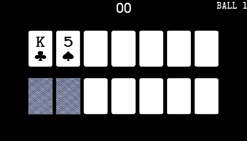
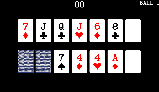
- Most money won: $5880, again by OLP. They must have been good at poker... This cash in also got them the 'Top Cashout' high score at 1,542,850. More than half their score from poker!
- Most hands won: 4. 4 is a pretty good game... I think the max I ever saw someone get during testing was only like 9, and they were familiar with the game and concentrating on just winning hands.
- Most hands played: also 4. So whoever played that 4 hand game had a 100% win rate, wow!
- Average cashout: 140k. This is slightly off since I realized that I had a minimum cashout of zero, meaning that anyone who lost points is going to be counted as just a zero, bringing the average up, but I don't think it'd affect it that much. Considering that the average score was 400k, I think this number is pretty well balanced. Maybe it should be a tad higher? I don't want the game's scoring to all come down to the end of game cashout, but also, it's Poker, you know?
- Average bonus: 50,000. This feels a bit too high to me, considering an average game is 400k. Almost half people's scores is coming from bonus? I'll probably have to tweak this a bit lower.
- Multiballs played: Hand: 84, Straight: 13, Flush: 10, Full House: 12. Nice to see that the three main multiballs all had similar play counts, but the discrepancy between 'Hand' multiball (the 'gimme' multiball for completing your first hand) and the rest is a bit higher than I'd like. When watching people playing, I noted a ton of people were lighting multiball but then not starting it. At first I worried they didn't know how to start it, but even when pointing it out, they still couldn't do it, so I think really the ramp shot is just way harder than I thought it was. I wish I'd made an audit for 'multiballs qualified' vs 'multiballs played', I'm sure it would be quite depressing
- Flubbed multiballs: 68. Also depressing... 68 of the 119 multiballs played scored zero points! I guess people just forgot to flip or something? There's no ball save so I know the multiballs can be short, but I'd expect most people to at least get to bat the ball around a bit. Similarly, not a single person got a jackpot in Straight multiball. I'd thought that one was easier than the jackpot for full house, but one person did get a nice 700,000 point jackpot from full house
- Most skillshots made: 7. That's a pretty good number. Again, I think the high ever was only around 9. Sadly this is counteracted by...
- Zero skillshots made: 232. That's not single skillshots either, that's entire games played where the player didn't make one skillshot. More than 50%.
- Biggest spinner rip: 58 spins. The average spinner rip is only around 20, so that's really amazing. Maybe they managed to combo it and get two hits in?
- Ball Times:
- Game Times: these were a bit lower than I'd hoped. I think optimally a game should last around 3-4 minutes, but the majority were shorter than 3 minutes. I'd put a lot of thought into trying to make the game easier for less skilled players, but couldn't come up with that many ways to do it without making it easier for more skilled players. A timed ball save would probably help here by just inflating the minimum possible ball time, but I'm not a big fan of them in games where you can plunge directly to a flipper, AND have savers on both outlanes to help you...
- Average poker hand win/loss: 1.47/1.05. Not bad. I guess at least some players are trying to play the poker a bit, otherwise I'd expect an even distribution
- Right outlane ball save used successfully: 68 times. Sadly this number isn't that useful without a 'number of right outlanes' audit, but it's nice to know that 68 people got to have the 'saved the ball using the popper' moment. When watching people play, this is probably the most exciting, successful moment that I saw
- Ramps shot: 99. Surprisingly low across 400 games, but people just seemed to have a ton of trouble lining up this shot for some reason.
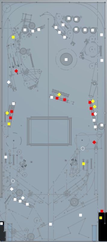
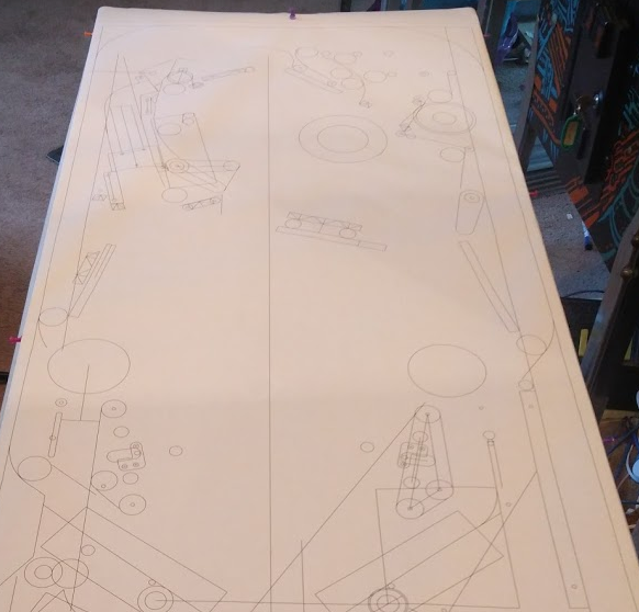
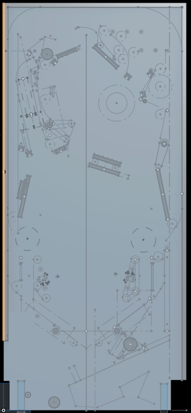
And finally, all my audit data, zoomed out to fit on screen
Cross posted from the original Pinside thread, this is one of many posts regarding my third homebrew pinball machine, creatively nicknamed 'P3'
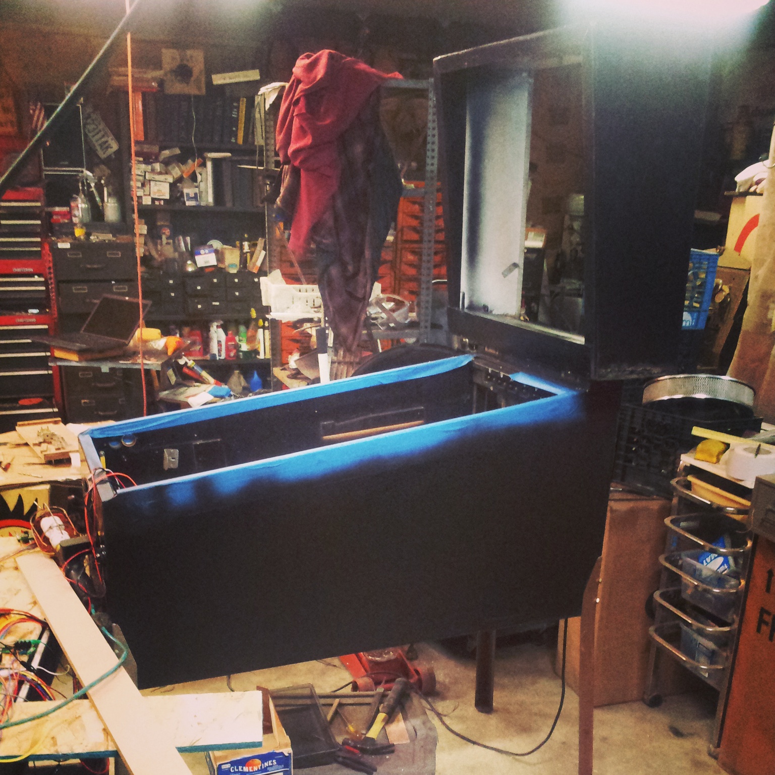
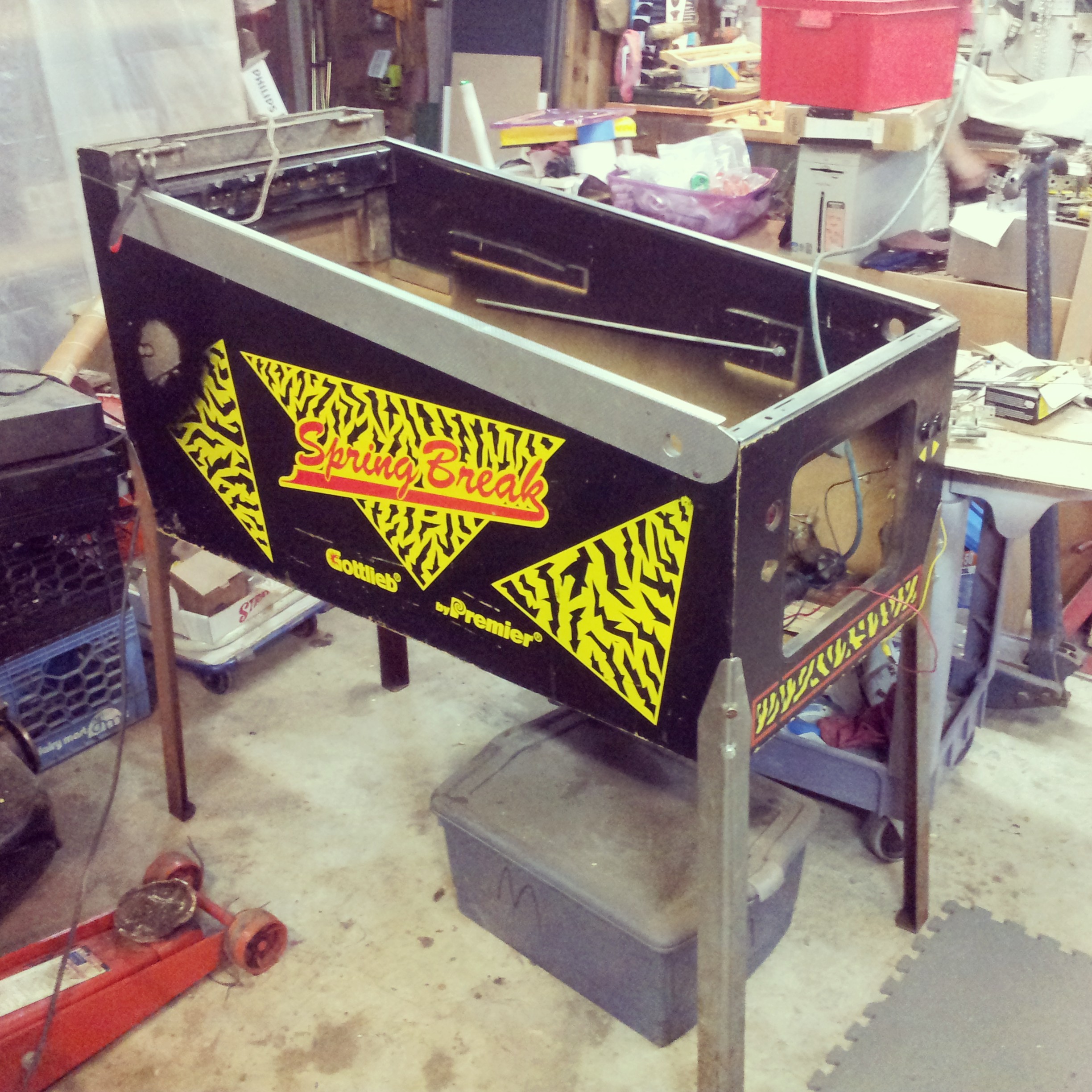
Heading to pintastic, I was mainly worried about three things: broken 3d printed parts, ball sticks, and something going up in smoke. I arrived early Friday morning and set the game up in the free play area:
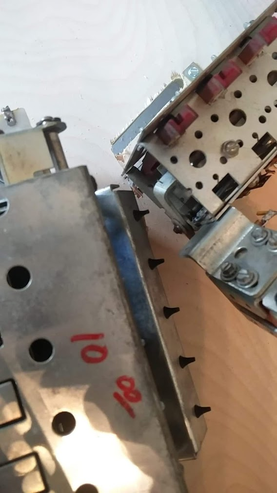
A quick inspection showed that everything had survived the journey intact, except that the upper 3 bank of drop targets had nearly worked its way lose from the playfield somehow. I'd never seen it come loose at all before, so this was a bit of a surprise, although considering that, for various reasons, it's only held in by two screws, I probably shouldn't have been so surprised. If any bank was going to do it, it'd be this one. It was at this point that I also discovered I didn't have any half inch, #8 wood screws, which I'd bought specifically to replace loose #6 wood screws (which is what I used for everything on this game) with in exactly this sort of situation. But I did have 3/8", and I reasoned that the thickness was probably more important than the length here, so I installed those. A few test games, and a quick chat with the creator of the Pincraft homebrew who walked by, and then I reset all the high scores and pronounced it "good to go" and left to check out the seminars.
I came back a half hour later to check, and the game was... still working! Had a few nice chats with players, and got a quick interview done by a youtuber, and then I left again. I tried to check on it every half hour or hour or so throughout the days, but I wasn't planning on really being there the whole time and sometimes I didn't get back for 4 hours at a time.
Issues encountered, day 1:
- about an hour in, I came back to check on it, and it was turned off! Uh oh, what could have happened? So I turned it back on and it all worked fine. No idea why someone turned it off, and didn't try to contact me
- soon after, I got a text that there was a part loose on the playfield. Turned out to be a random 1/2" wood screw. I searched all over the game but couldn't locate anywhere missing the screw, so I just tossed it in my spare parts and closed the game up again
- another text, another part loose on the playfield. This time it was the spring off my left inlane gate. There's nothing holding this on besides gravity and friction, so I'm honestly surprised this had never happened before but, more than a year of testing and it didn't, so I never worried myself about improving it.
Oh well. I put the spring back on and we're good to go
- came by, a player was trying unsuccessfully to start a game. "Ball Missing". Oh boy, we finally have a ball stuck! I confirm there's only 2 balls in the trough. Search high and low all around the playfield... no ball. I finally find it in the coin box area, sitting right on top of one of my boards, but no damage luckily. No clue how it possibly could have gotten down there.
- another part on the playfield. it's the spring again. I reinstall it.
- game has crashed. The cause? No space left on the SD card; my debug logs have filled up the entire 32GB. I sorta knew this was a possibility, but besides from turning off the logs I hadn't found any good solution since I can't delete the old logs while the game is running easily. I delete the logs and restart the game, problem solved.
- another part on the playfield. it's the spring again. Grr. I wonder if maybe the spring has gotten stretched out over time, and replace it with a new one. Maybe the extra tension will hold it on well enough?
- while showing the game to someone, I notice that the left outlane diverter gate is stuck down. Did the mosfet blow? Nope, it's being PWMed properly to stay down, so the driver board software is working properly. The game software thinks it shouldn't be engaged though. Something must have gotten out of sync between them, so I restart the software and it resolves the issue. No idea how long it was like that, but the coil still hadn't gotten hot, so I guess my PWM settings must be pretty good. I'd considered just having the gate stay down during play (vs turning when the outlane switch is hit) but had been worried the coil would eventually cook, so I'd avoided it. Might be worth another look since I've been having issues where the gate doesn't turn fast enough to divert balls
- someone reports a stuck ball. hopefully it's not in the cash box again. nope! It's... stuck on the left inlane gate. the new spring is just strong enough that a very slow ball isn't heavy enough to push the gate open. I try to stretch the spring a bit and find a happy medium between the two and cross my fingers
- finally, near the end of the day, I again get a stuck ball reported. This time it's sitting in the outhole, and not getting kicked over. I worry there's a switch issue, but it turns out the coil fuse for that bank has blown. I replace it and get ready to turn the power off quick once I see what's locked on but the game works fine. Not sure what blew the fuse. Looking at it, it's a fast blow, 4A. In retrospect that probably should be a slow blow to account for random situations where too many coils just happen to fire at once, but it's never been a problem before, and I'm wary of swapping fuses at the event, so I put another 4A in.
Day 2:
- while showing the game to @McSquid, the left drop target bank starts having trouble resetting. Luckily, my code will retry a few times and then give up, so it's not a huge deal, but after the game I check it out and see that it's starting to come loose like the 3 bank did the previous morning. Again, this is a bank where I had to remove one of the 4 mounting brackets to make it fit, so maybe that's a problem, but there's not much I can do about it. I swap in some #8 screws just in case
- a few hours later I get a report that the game is 'stuck'. When I get there it's sitting on the bonus collect screen, but not counting down. Somehow, the bonus 'total' that's supposed to be awarded has become NaN, which basically means a divide by zero or something happened somewhere. The game keeps trying to subtract 1,000 from the total and give it to the player, but when you subtract something from NaN you get... NaN. Not sure what caused it, but a reboot fixes it.
- a couple more uneventful hours pass, and the NaN bug strikes it's head again. Weird that this didn't happen on day one, but twice on day two, but nothing I can do about it right now
- another part on the playfield. it's the spring again. I reinstall it. Looks like this will just be a thing for now. I'll try to make a new version of the gate with some little overhang to hold it on in the future
- around 8pm, the fuse blows on the outhole again. Still no idea what's causing it, but again just replacing the fuse fixes it. I suspect that maybe the left outlane gate (which is on the same solenoid bank) might be stressing out the fuse when it gets stuck on, and that combined with some other coils may be blowing it?
And that's it! Not a single broken 3d printed part. No smoke. Not even any real ball stick areas for me to address. The game was received pretty well; a lot of praise for the lower flipper and the right outlane VUK/popper once I explained it.
That's probably my biggest 'failure'/takeaway from the weekend though... Most people didn't pick up on any of the more advanced features/rules I'd worked in while playing. A lot of people got confused by the secondary flipper buttons for the magna save and popper, and I'm reminded sadly of the new Black Knight's action button magna save. Not many people actually picked up on how the poker hands worked, or at least, they didn't have the flipper skills needed to actually aim at good cards. Most people just flailed around at the targets and got random hands, then double flipped through the 'end of hand' animation without even noticing if they'd won or lost. Also, very few people figured out the skillshot. Most just full plunged, which tended to send the ball flying all the way around to the left inlane to their surprise. I thought I'd done a pretty good job of making the skillshot obvious, flashing the lights brightly, etc, but apparently that wasn't enough. It's a bit saddening to see, but I guess that's just how a lot of players are. I don't really plan on changing anything on that front though; I didn't design this game with the 'mass market' as my goal. When possible I've tried to make it so the layman player can also enjoy the game as much as possible, but I'm not going to remove features that expert players can enjoy just because they may slightly confuse other players.
Cross posted from the original Pinside thread, this is one of many posts regarding my third homebrew pinball machine, creatively nicknamed 'P3'
Finally got the game set back up again after its trip to Pintastic, so an overview of the past few weeks...
I didn't want to mess with the functionality too much since things had seemed mostly solid, so once all the art was done, I tried to focus on finishing touches.
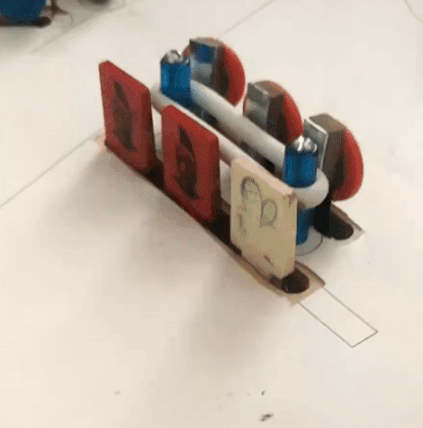
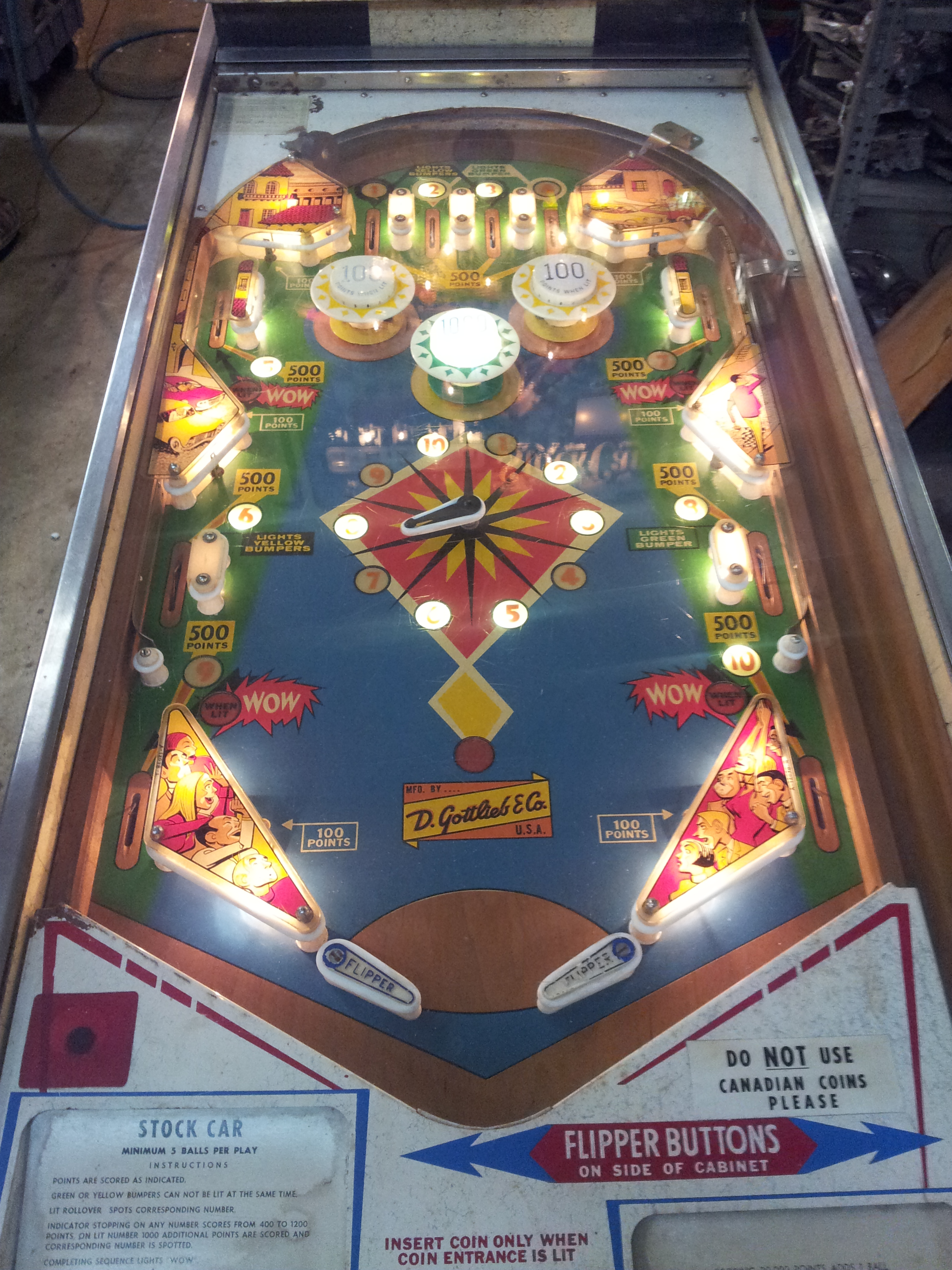
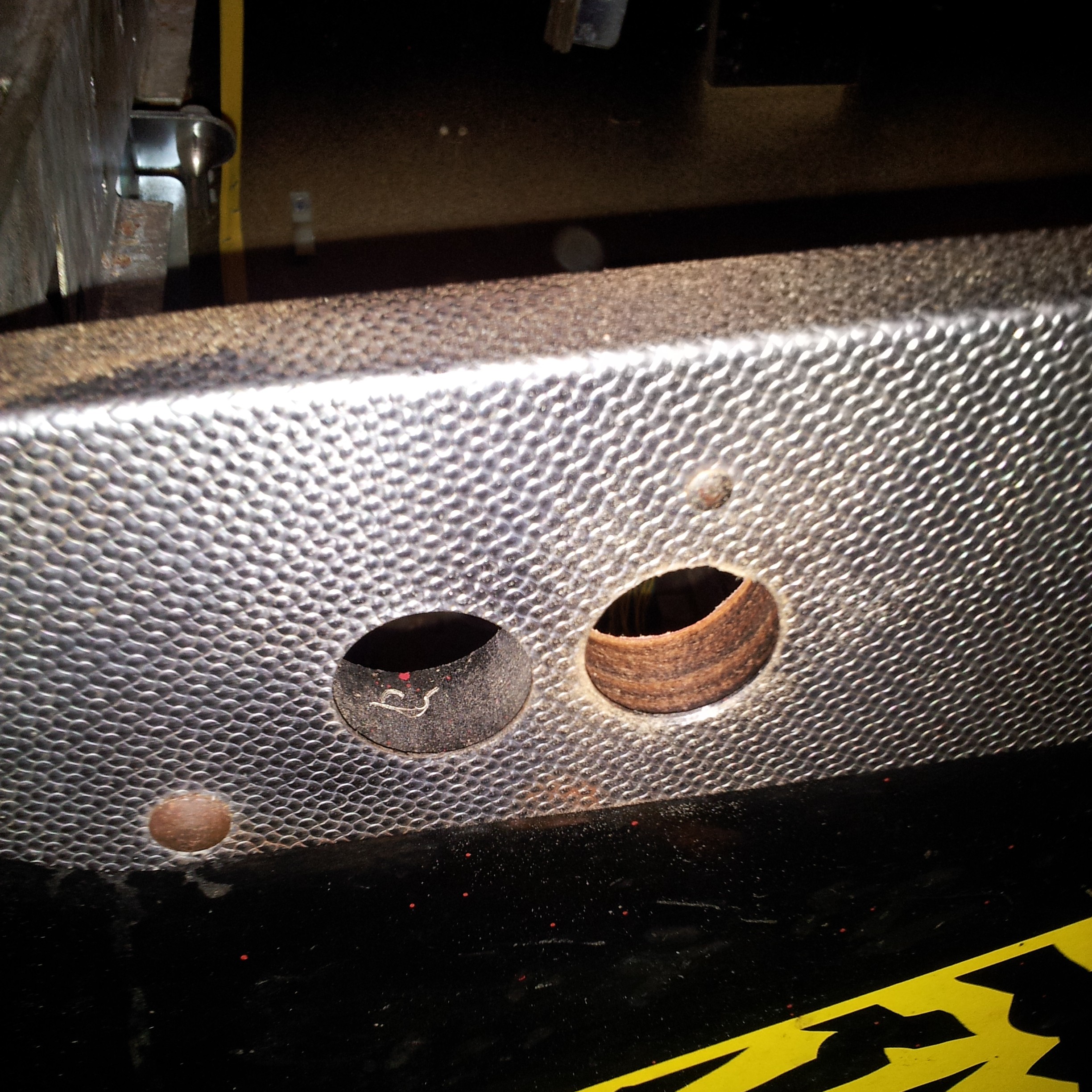
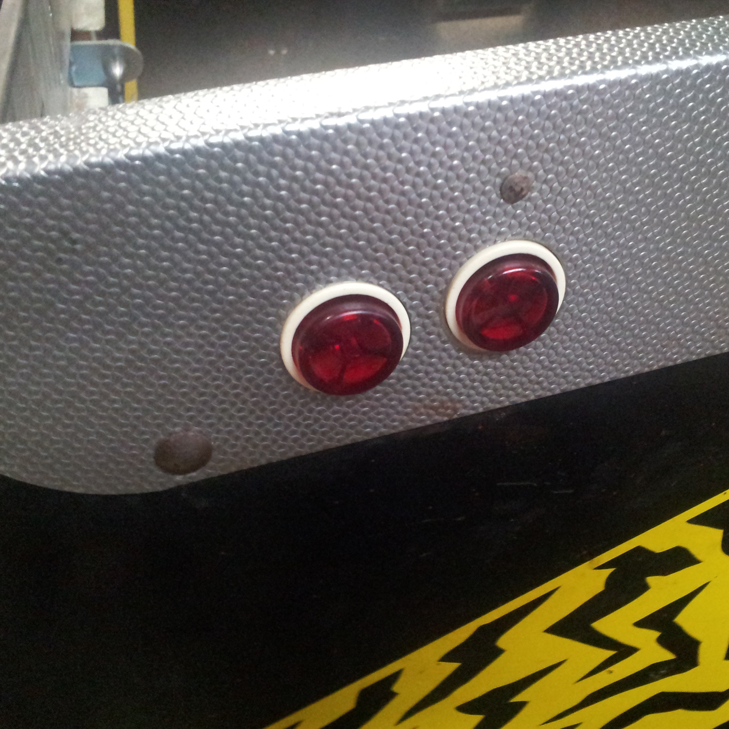
I wanted to cover up the apron since it was just a clear piece of plastic and a bit ugly, so I had the random idea to just use green felt like on a poker table. And what goes on a poker table? Chips! These are just super-glued together, but they're holding up alright. With the lockdown bar and instruction card on, it doesn't stand out too much
At the request of a tester, I added a quick shooter gauge. I would have liked to use an existing one from a game with some nice art, but none fit the weirdly shaped bottom corner I ended up with...
And, as a last finishing touch:
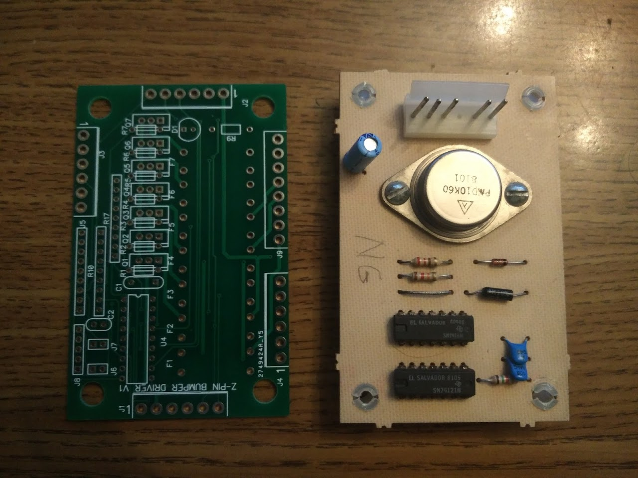
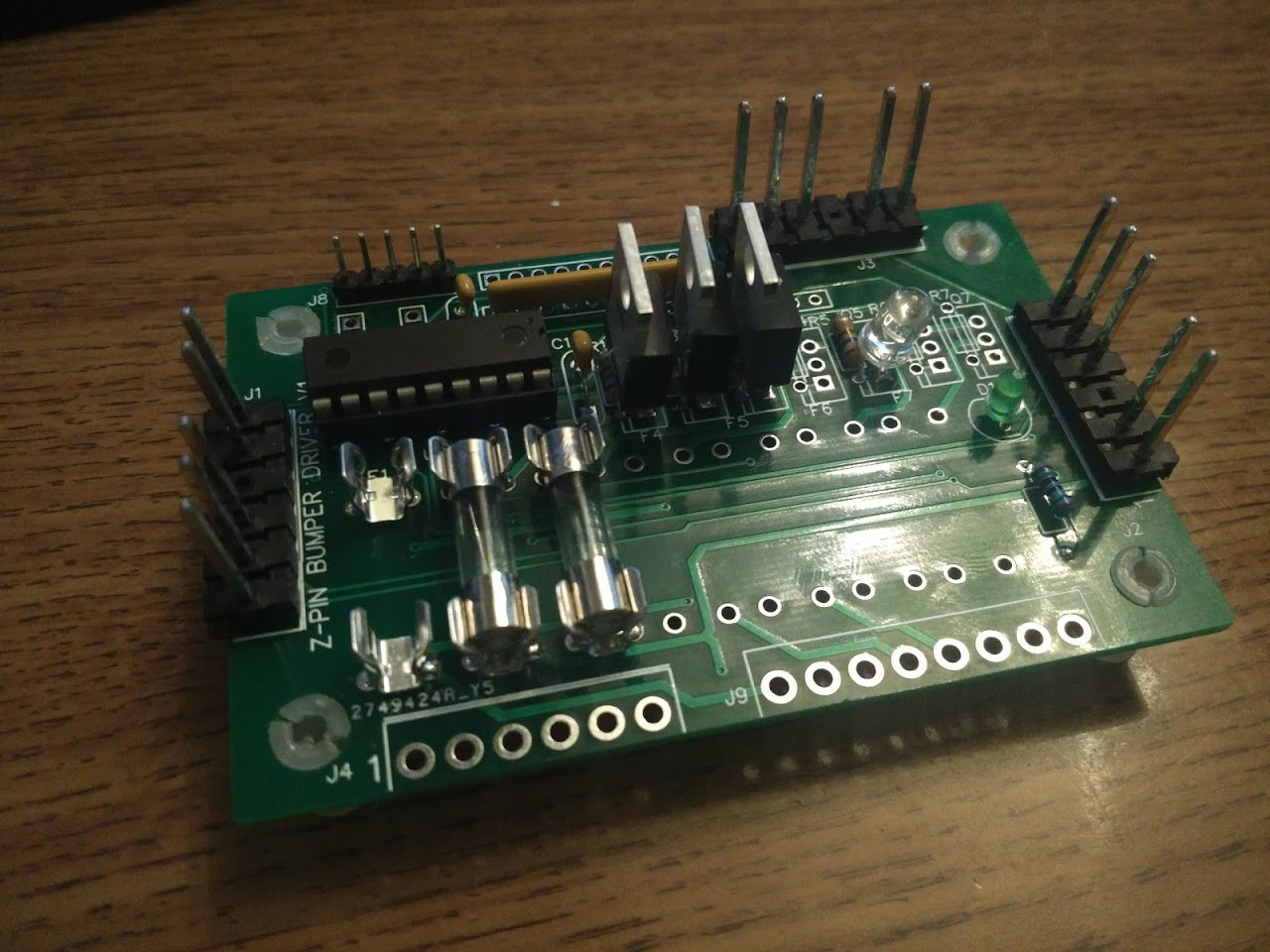
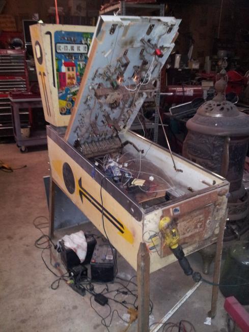
Leading up to the event, I had a few people by for last minute testing. This mostly went well, just a few bug reports, and mostly not game breaking, so I was able to resolve the important ones in time. With just 2 days to go however, suddenly the game completely died. No lights, no displays, and half the coils wouldn't fire. Eventually I found that the 5V fuse had blown, which would explain why the displays and lights died. I'm not sure what caused the fuse to blow, other than that I found one of the power connectors the for the displays had come off the board, so maybe it somehow brushed something? But it's not really a connector with exposed metal or anything. Anyway, the 5V also powers the mosfets for the solenoid drivers, so without that, some coils weren't getting enough power to fire. Sadly the way that they were getting power was that they were somehow powering themselves off the 3V from the CPU chip through their inputs, which managed to also smoke the CPU from the stress, so I basically had to rebuild both driver boards. Wish I'd noticed that I'd blown a fuse quicker, but not really sure what to do about that problem overall, so instead I just packed 2 spares of every chip used on the boards, in addition to a whole spare driver board, and crossed my fingers that'd be enough. Next game I'm going to try to move to a completely different architecture for driving my mosfets so hopefully this won't be an issue anyway.
Besides from spare chips and driver boards, I also prepped 2 spare Raspberry Pis (although I've never had one of those fail) and 3D printed spares of every single part in the game, since I wasn't sure how the 3D parts would hold up. I've had some games at shows get 200+ plays in one day, and looking at my audits, I've played less than that many test games during the entire development cycle, so despite the game being mostly solid for the past few months I really was moving into new territory.
Cross posted from the original Pinside thread, this is one of many posts regarding my third homebrew pinball machine, creatively nicknamed 'P3'
With a month and a half to go until pintastic, I was in a pretty good spot. The game was working fairly well, I had most of the features done and lots of issues worked out. I figured it'd just be finishing touches and bug fixes, and I was actually ahead of schedule! So then I got to thinking if there was anything else I could do in the leftover time. One thing that'd stood out from testing is that my pencil-drawn instructions and labels on the playfield weren't readable enough for people to notice. So I figured maybe I could draw up some simple text boxes on the computer for those. Using some gottlieb EMs as reference, I found out what font was usually used, and tried to copy some of their basic styling, and I drew some stuff up in inkscape
Those didn't look too bad! So I got a bit more adventurous with some of the other instructions I had.
But I needed to figure out how to get those onto my playfield... When I first started drawing these I'd figured I'd just get some "clear sticker paper" from Staples, but it turns out that... doesn't really exist. I ordered a few things like projector transparencies and decal paper, but those also didn't work out. Everything ended up transparent still, not opaque ink on a clear background, so they didn't look too good
After a bunch of searching, I figured that what I really wanted might be "window decals" which... aren't decals. They're just vinyl stickers. I ended up ordering some from signs.com since they were the only site I could find that had an exact scale option. I got both decals and window cling, thinking that the decals might rip up the wood but the cling would have a weaker adhesion, but it turned out the cling couldn't stick to the wood at all, and the decal's stickiness wasn't too bad
The decals went on fine though, and had pretty good 'blocking' so the woodgrain didn't show through, although some of the pencil was barely visible in some of the lighter colors so I had to go back and erase all that.
With that looking pretty good, I went ahead and spent a few evenings drawing even more instruction blurbs. And then got on a bit of a roll I did a few smaller things like keylines for all the inserts. And some graphics for the magna save, and around all the displays. And then I did all the major shots and lanes too because why not? Now I had to tear down the whole playfield to install all these.... Most of the small ones weren't too bad. The larger ones (some are up to 20 inches long) got a bit more complicated though, especially the ones that needed to line up with lots of different playfield features. I'd never really done decal work before so I had to figure it out a lot as I went, but luckily they were forgiving enough that I could peel them off a few times to get them right before they started to loose their strength, and were slightly stretchy too so I could bend them a bit to line things up. That stickiness also became an issue though when I tried to put some over the displays, and the stickers started to sag down over the hole.
I ended up having to cut out some spare plastic sheets to cover the displays with in order to support the stickers. Then a new problem was revealed, as the backlights of all the displays had some light bleed that was showing through the stickers and didn't look too good, so I had to mask off portions of the plastic with electrical tape
There was also a few issues with the center, clear portions of the stickers not adhering to the plastic perfectly, creating bubbles or trapping little bits of dust, so I also had to manually trim out the center portions with an exacto knife in some cases
The biggest challenge, however, was also the biggest sticker. Somehow this massive part, which I couldn't find some way to split up, didn't come out one-to-one scale, despite being in the same file as everything else
The piece should be 23x8", but instead it was 24x8.5". A small enough different that I didn't notice it during proofing, or when I got the sheet, until I cut it out and actually put it on the playfield. And since it was the biggest, most complicated piece, I saved it for last too At this point, there was under two weeks until pintastic. It'd take at least 2-4 days for another decal to be made, plus 3-5 days to ship, and I still needed to reassemble everything and do a bunch of final testing, so I didn't have time to wait for a replacement. At first I figured I'd just leave it off, but that one decal was basically a whole quarter of the playfield, so it was really obvious. In a flash of 1am, "nothing left to lose" decision making, I decided to just cut the whole decal up by hand and rearrange it to fit.
This went... much better than expected. In the end the one decal became 16 separate pieces, which I then cut apart, layered, and stuck back together so that all the keylines still matched up. Close enough! With the plastic protector over it you barely even notice. It'll be fun showing it to people and seeing if anyone asks about it. I've ordered the correct decal, along with a few other corrections too, so the next time I do need to tear the playfield down and get the protector off, I can replace it.
Since I was already ordering from a printing place, I also got some reverse-printed decals for my plastics
They weren't quite as vibrant as I'd hoped, but still much better than my inkjet-printed ones are. Plus they're adhesive, so the paper doesn't sag under the plastic. Before:
After:
Aaaand... done! I wish I'd been able to come up with a few more bits of actual art besides the one hand of cards between the flippers, but I wasn't able to really find anything else that fit with the theme and art style so far.
Cross posted from the original Pinside thread, this is one of many posts regarding my third homebrew pinball machine, creatively nicknamed 'P3'
Falling behind on updating this thread as the final crunch intensifies
Lots of little things going on...
I've been trying to track down all the 3D models I used for the build to print up spares. In a few cases I can't actually find the original file anywhere! Not sure what to do about that, as I thought I'd been tracking everything fairly well, with consistent naming and versioning. A few small things I had to re-model, or I'm stuck with just the generated g-code and I can't really edit it anymore.
With some plastics with art on them, I figured the mismatched drop targets stood out a bit, so I made some quick stickers for them
In a bunch of places I had holes in the playfield where I'd installed features and then removed them later, so I'd just taped some paper over them, but that was also a bit ugly.
Luckily, I had some scans of the playfield from before I'd cut many of the holes, so I printed out stickers of the wood grain and covered them up
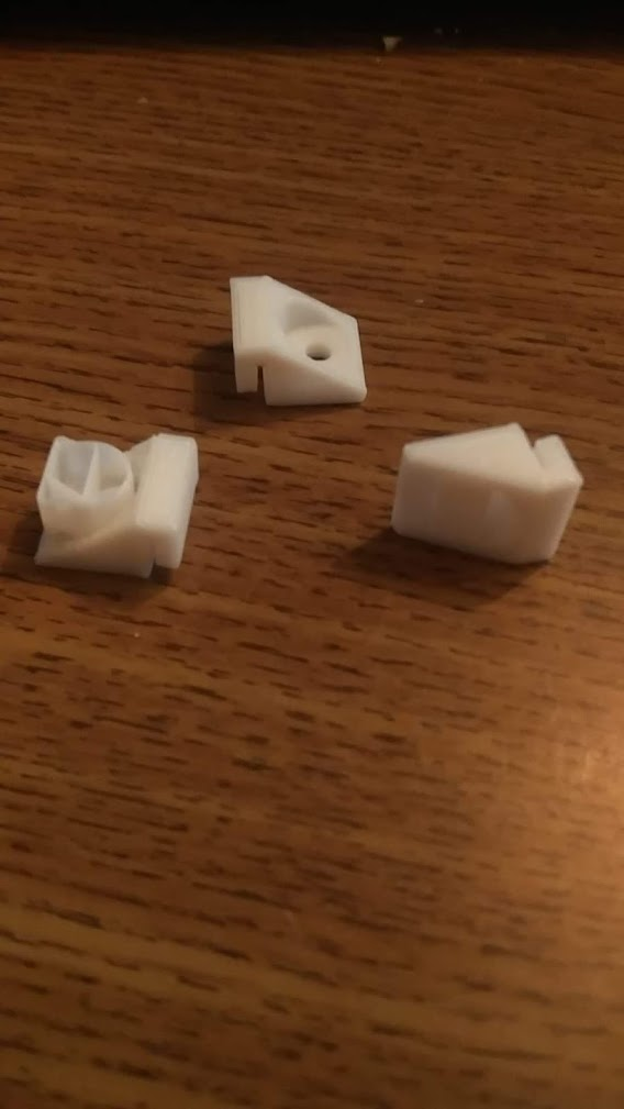
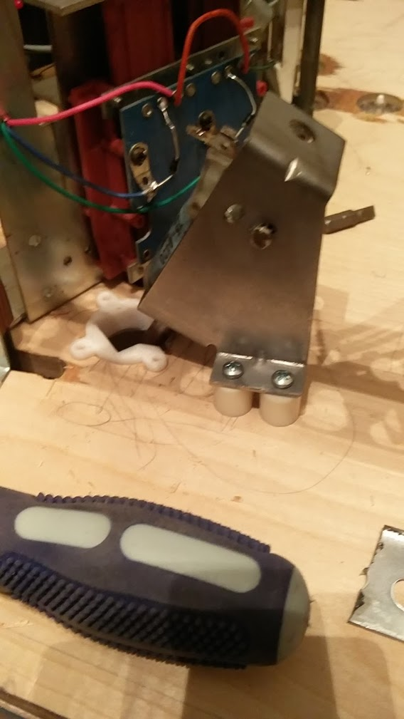
As more playtesting got done, I started having issues with a few connectors falling out of stuff. Usually I'd used connectors with latches/ramps to prevent that, but in some cases I couldn't. So I 3D printed some little braces to hold stuff in
I did a bunch of little quality of life things in the code. Hold start to end game. Tweaks to a lot of switches. More instructional text. A lot more feedback as stuff is happening, like these little blinks when you hit something to help you know it wasn't a near miss or something
Cross posted from the original Pinside thread, this is one of many posts regarding my third homebrew pinball machine, creatively nicknamed 'P3'
While out shopping, I saw a Cri-Cut for sale, and thought "that would be handy to cut some stencils!". But then I thought: "wait, why do I need stencils? what if I just cut the art out of vinyl directly?" So I grabbed a roll of 'removable' adhesive vinyl from the supply area and tried it out on the cab. It looked fine, and seemed to peel back off without damaging the webbing, so that sounded good. Except I didn't want to drop $300 on a cricut. So I bought a $10 'drag knife' vinyl cutter attachment and hooked it up to my CNC router instead
Took a few tries to get everything adjusted properly and figure out a workflow, but once I worked out the kinks it worked quite well.
Hand positioning and applying them to the cabinet also took some trial and error, but no major issues
As always, learning that even a tiny bit of art goes a long way. I'm not going to win any awards here but it's turned out pretty solid despite my zero art skills
Cross posted from the original Pinside thread, this is one of many posts regarding my third homebrew pinball machine, creatively nicknamed 'P3'
Usually people spray cabs to paint them, but I don't really have the space to do that, so I opted to try using a roller. I set up a tarp in the middle of my game room, put the cab down on it, and applied about 6 coats of paint, sanding between each few. The texture from the rollers sanded off pretty easily in most places, but I still had a lot of places where the sanding wasn't doing much. I think this was more to do with the wood than the painting though. If I was doing a proper restore I'd have used more filler and stuff to get everything flatter so that the sanding would hit evenly. Also I'd have a power sander instead of just a sanding block. Whoops. I'm not aiming for perfection though, as long as nothing doesn't look like an obvious mistake, I'm okay with it.
After my quart of paint ran out, I decided to try to do some webbing like many EMs have. Both because it looks cool, and because it'll probably help hide more of the imperfections in the base coat and wood. I saw a few people recommending Montana 'marble effect' spray paint with good results, so I gave it a shot here. Originally I was going to bring the cab out in my yard to spray it, but because of the weird way that it works, even a tiny bit of wind messes it up, so I had to do the spraying in doors :/ Luckily with a bit of 'masking' around the sides I was able to do it without any mishaps.
With my black stern siderails, black painted lockdown bar, and some black legs and shooter rod housing I picked up, the white really pops; I'm pretty satisfied with how it turned out overall
I still need to figure out the stencils for the side art to go on top of this, so that'll be a task for another day. I figure I'll need to mask those anyway, so it doesn't hurt to have the rest of the game reassembled when that happens, and in the mean time this looks leagues better than the peeling whirlwind art that was on it before
Cross posted from the original Pinside thread, this is one of many posts regarding my third homebrew pinball machine, creatively nicknamed 'P3'
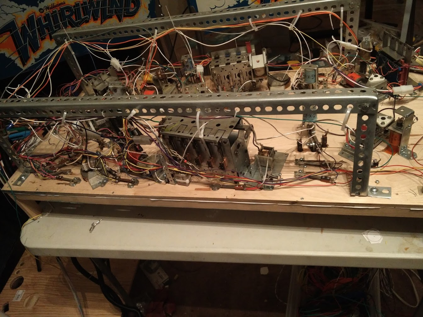
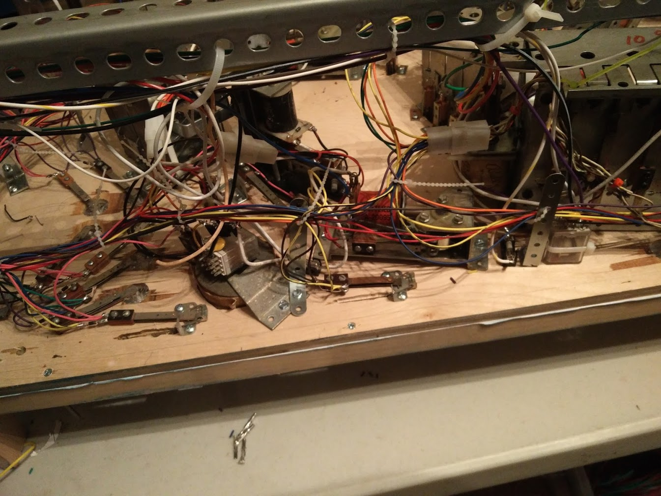
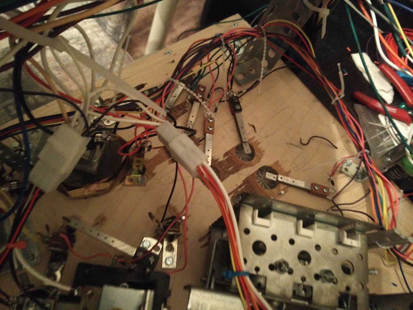
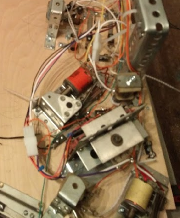
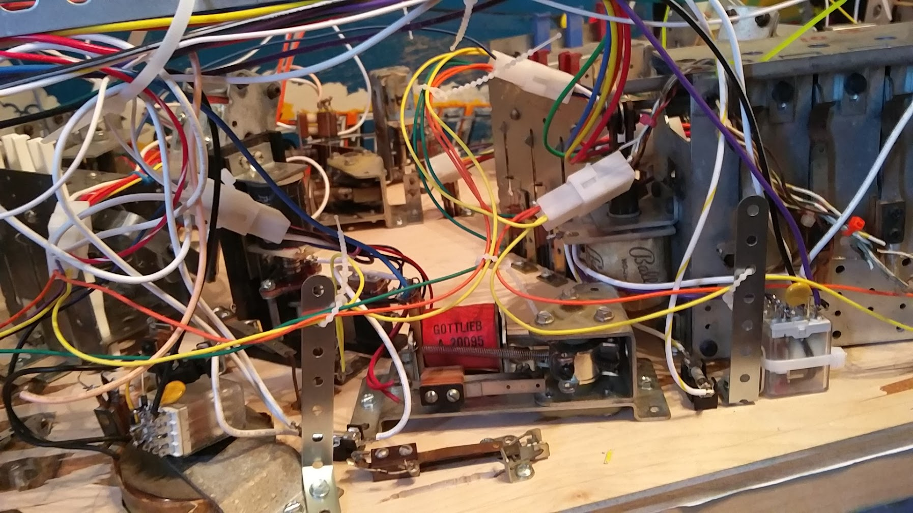
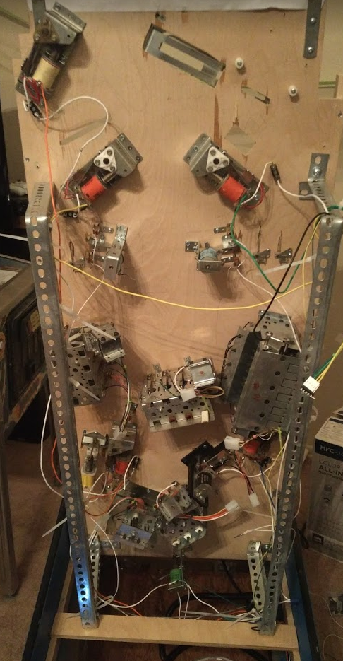
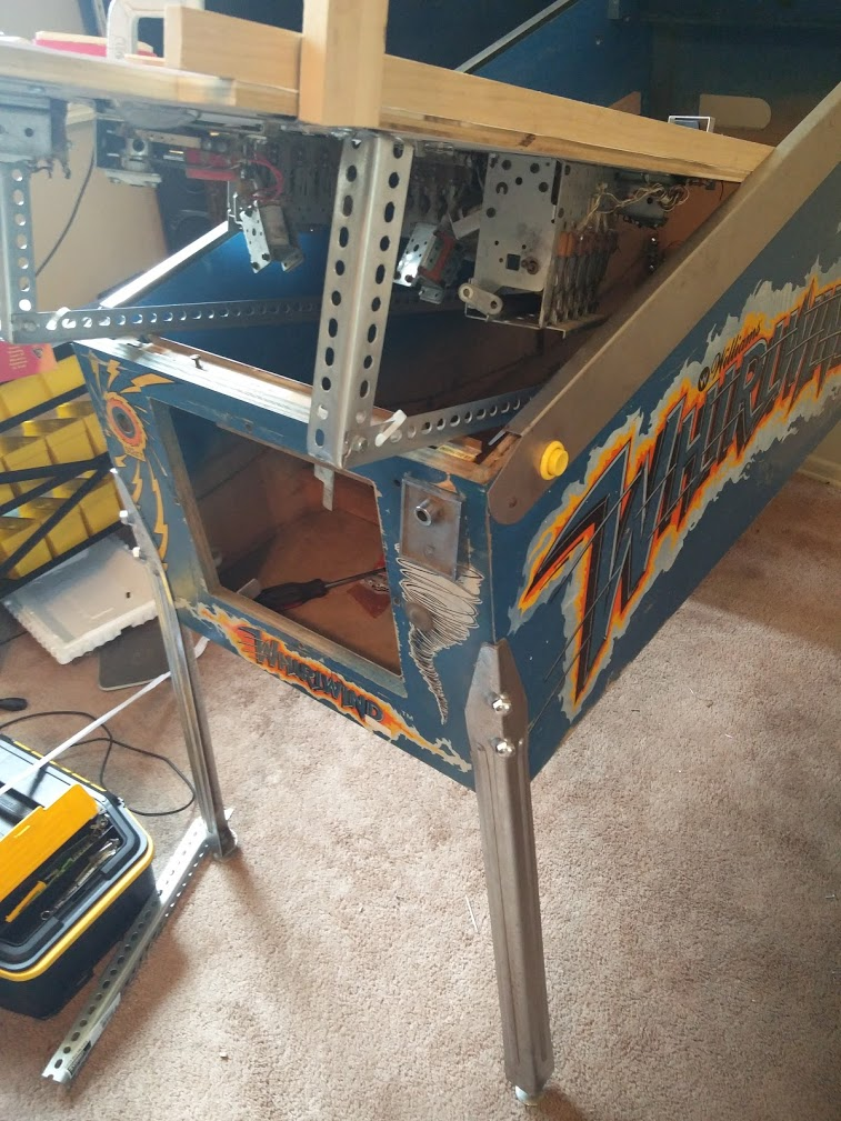
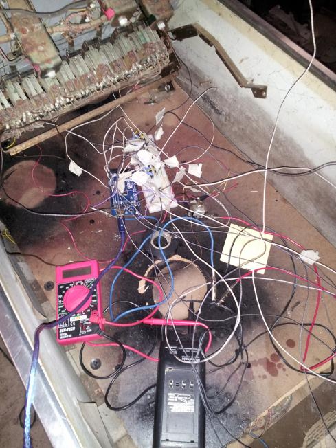
Since things were looking pretty good as far as my pintastic target, I decided to make a questionable decision and try to get some cabinet art in too. First, I took out the playfield and neatened up the cabinet wiring some more.
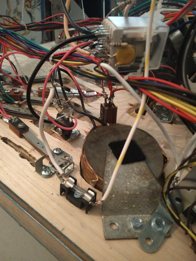
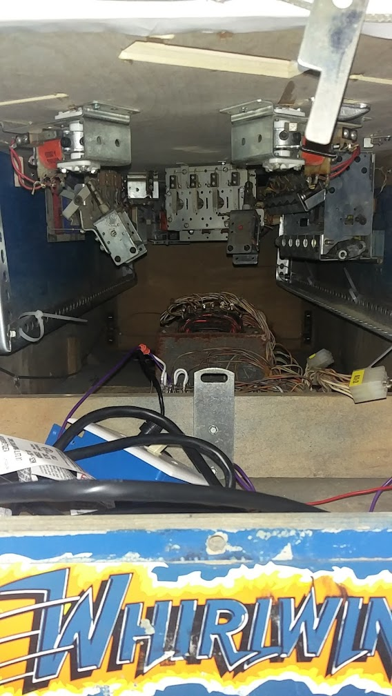
It still doesn't really look that neat, but everything is actually routed around and attached down, so I'm not really sure what more can be done on some fronts. Part of the mess is probably just the weird way everything is arranged and packed in, plus a lot of premade components that weren't meant to go together like this, like all the extra wiring on the transformer and power supply, or the USB, HDMI, and ethernet cables that I can't really chop down to their exact lengths easily.
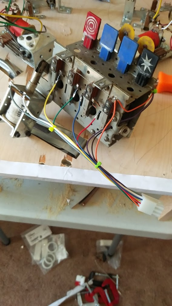
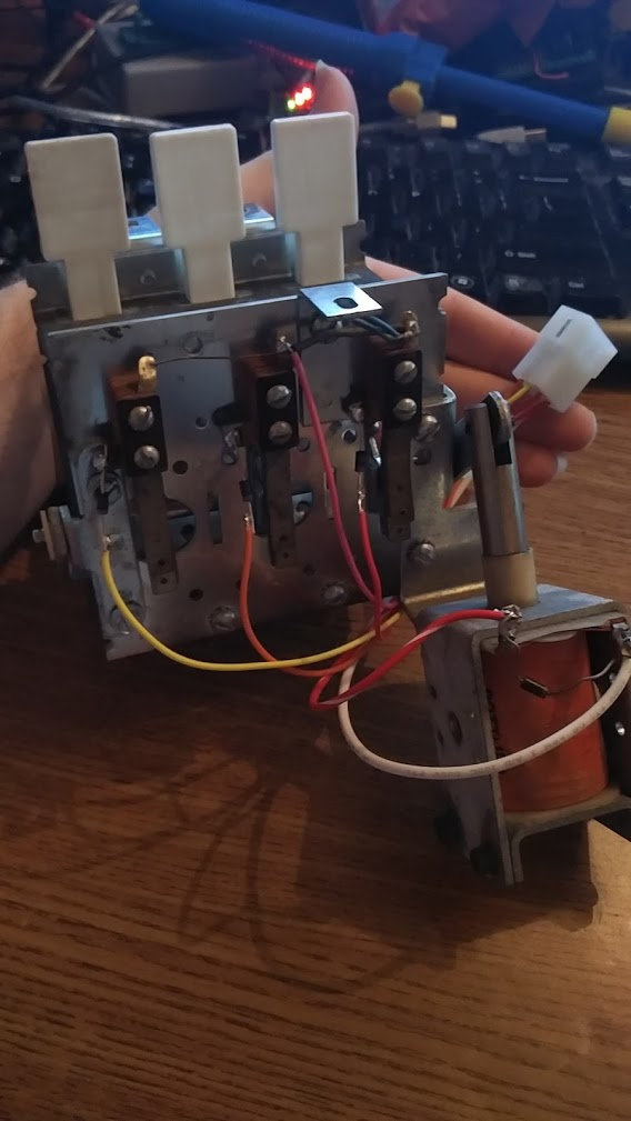
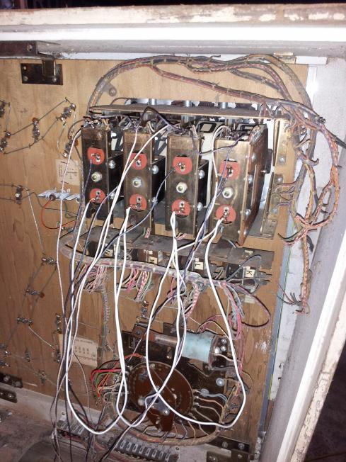
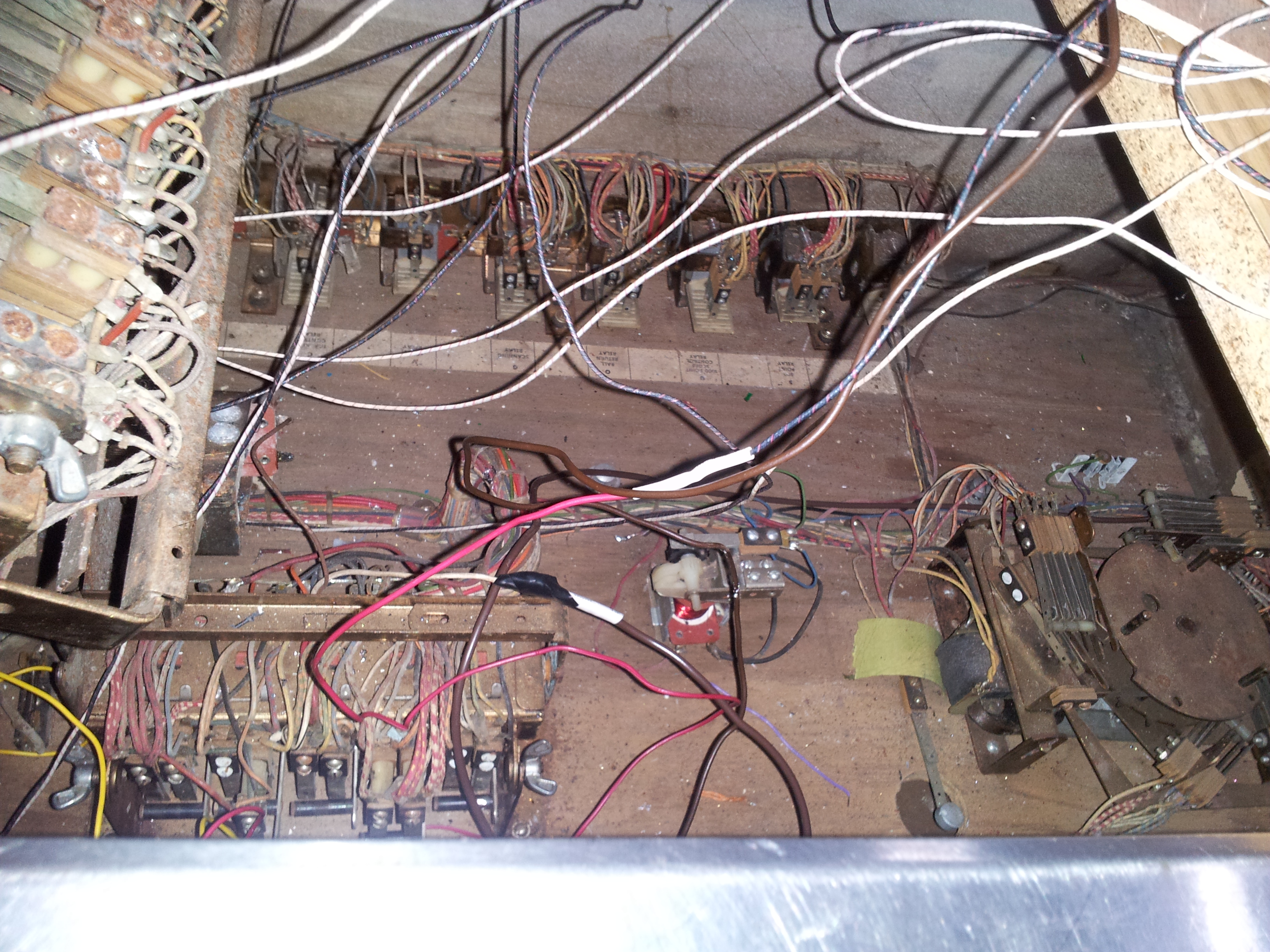
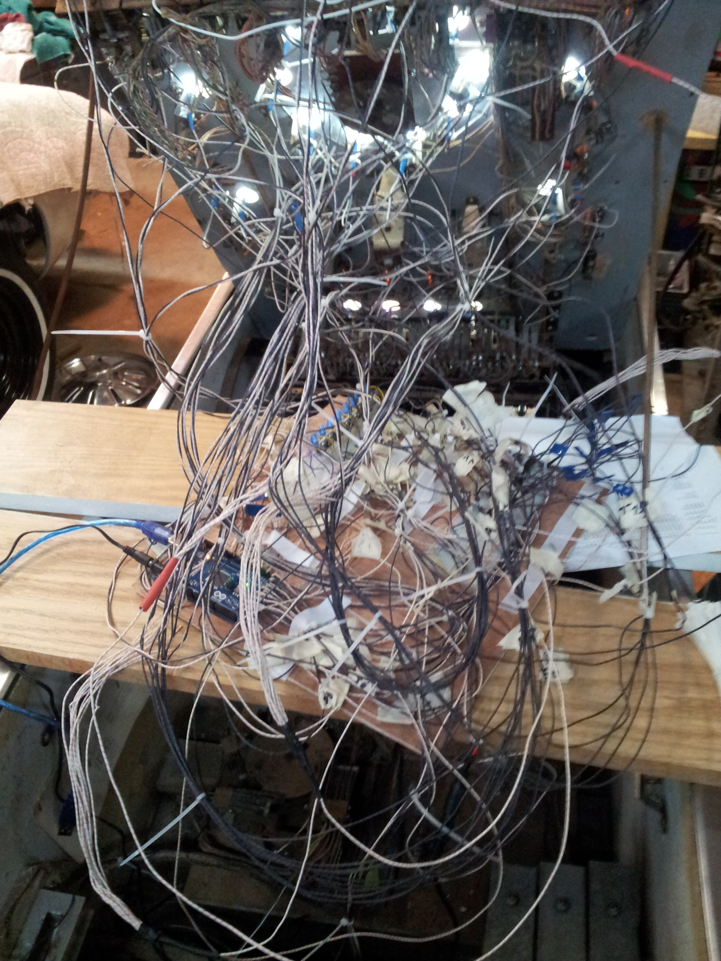
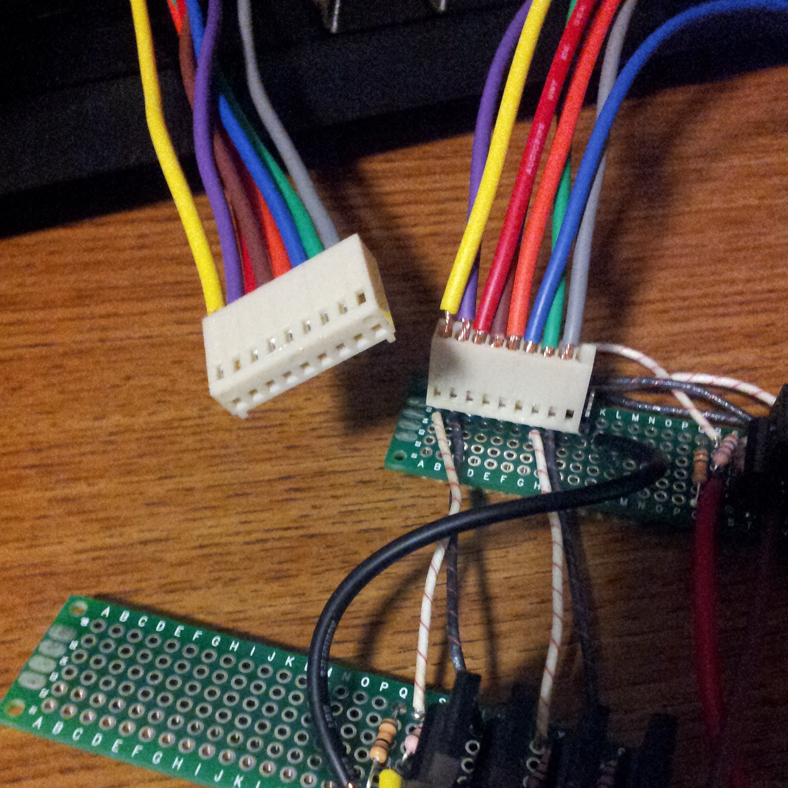
The playfield wiring also isn't as neat as I'd hoped. When I started this project my plan was to have just two connectors going from the cabinet to the playfield: one for power and one for data. The driver boards were all going to be mounted to the playfield like on a Spike game. Instead I have two big black hoses full of ~30 separate solenoid power lines snaking all the way to the driver boards in the cab. My single power connector became two since I separated out the low and high voltages. And instead of a single 'data' connector, I now have an ethernet cable, an hdmi cable, a switch matrix cable, and a led cable. Those last two probably could have been combined, but there isn't much I can do about the others since they're standardized. All of that winds up as a lot of connectors (14 at last count) that I need to unplug and remove from their routing to remove the playfield
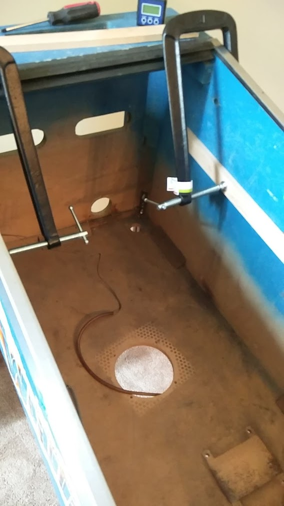
With the playfield out I was able to take the cab down to get it sanded. That also meant I finally got to clean it out a bit. A lot of random stuff accumulates at the bottom of a pinball cab when you're building a game in it!
Now, time to sand it down:
Next stop, Home Depot to buy some paint. I've never done a cab 'restore' before, so this should be interesting
Cross posted from the original Pinside thread, this is one of many posts regarding my third homebrew pinball machine, creatively nicknamed 'P3'
I scanned the plastics I had in with my printer and started mocking up some simple art using a CC vector playing card art pack I found online, then just printed them out on paper for a test
The paper didn't really turn out that great. Colors were very muted compared to how they look on screen, and without being glued to the plastics it still sags a bit and looks a bit messy, but they still really help pull the playfield together. I'd like to try to make up a few more paper bits to put on the playfield itself, at least where my hand written rules currently are, but that'll have to wait until I take the plastic off again. I've basically given up on ever having full playfield art for this, but I think a splash of color here and there should be more than enough. Once I've got the rest of the plastics made/mounted and drawn up I'll get them printed professionally somewhere for some better colors.
Cross posted from the original Pinside thread, this is one of many posts regarding my third homebrew pinball machine, creatively nicknamed 'P3'
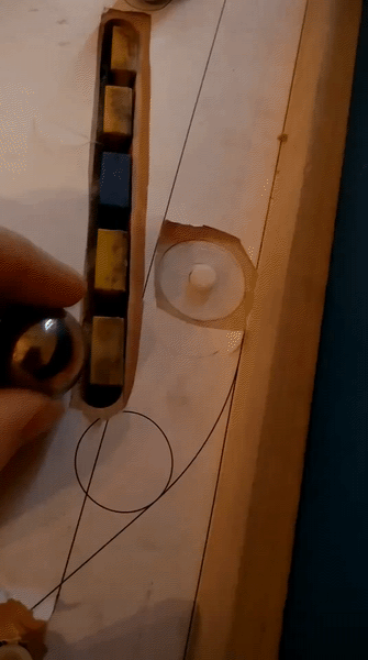
One thing that didn't cause any issues during testing, much to my surprise, was the lack of plastics. I thought for sure some airball would end up sitting on top of the slings, or manage to fall into the apron area since there's no apron, but that didn't happen once. Nevertheless, it needed to get done. I started by just sticking some index cards on the posts, and hand cutting them roughly to fit the shape
Once I had a few forms ready to test, I grabbed some scrap material from my last playfield cut to practice cutting with scissors and see how clean I could make them. Before I could actually get cutting though, I realized that one of the scraps I'd grabbed looks a lot like my slingshot.... Because it was! Not sure why I didn't think of it sooner, but obviously if you cut out a playfield protector, the left over 'negative' space will be sized to the unplayable areas, which is where the plastics need to go anyway.
So I drilled a few holes for the posts, peeled off the protective layer, and then drew a border with dry erase marker so they'd show up, and:
Not bad! The left sling went the same way, but I needed to manually cut out a bit to fit the gate in Most other plastics weren't so clear-cut, but I was able to eyeball it and get them to fit without major issues
Even the apron was almost ready-made once I chopped it out of the scrap border plastic, although it's not perfect as I had to leave a hole for the handle.
I don't have any 'front' wall for the apron yet either, so I guess technically an airball could still get up there and end up stuck between the apron and the glass, but that's still much better than it falling in and potentially hitting the mechs or something
One thing I hadn't really counted on was the actual mounting for the plastics. For the slings it wasn't too complicated as I just needed to swap the phillips screws for standard pinball ones with a 6-32 thread on top, but many places were made mostly out of mini-posts, which I used since they have the smallest diameter, allowing me to fit more stuff into some tight spaces. They worked great for that, but since they have a pointed top I can't use them to mount plastics, so I'll need to swap some of those out. Trouble is, no one makes a similar post with a wood screw on the bottom and a threaded top, so I may need to dig in deeper than I was hoping and start installing some t-nuts and machine screws. I didn't really plan the playfield with that in mind beyond a normal "well I can swap to machine screws later if the wood strips out", so a lot of those posts are above mechs and may need to have the t-nuts recessed or other annoying things.
Cross posted from the original Pinside thread, this is one of many posts regarding my third homebrew pinball machine, creatively nicknamed 'P3'
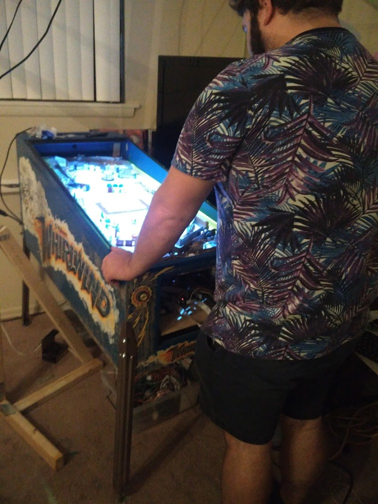
Had a small get together at my place last weekend, and had the game set up and playable during that time, with a camera on it. I recorded about 12 hours of video, although some of that time it probably wasn't being played... Twice I had the solder break on the flipper wiring to the resistors. I'll need to think of a better way to mount those. Currently they're just hanging awkwardly from the coils from when I first attached them for testing, which obviously is bad. Once the flippers just died randomly, and came back next ball. Not sure if that was a tilt or something correct that the player didn't notice, or if something malfunctioned. Will have to track it down in the recording and see. One time the ramp switch didn't register, which has been a recurring issue. I've got it tweaked 'just right' so it's 99% good, but I need to figure out a better solution eventually. This wouldn't be too big of an issue, except the lock post in the ramp won't let the ball back down, since it doesn't know it's there. I had two other stuck balls, both times they were caught by the shooter lane diverter, pressed against the back of the drop target next to it. Both of these issues will at least be alleviated by a ball search, which I'd never gotten around to coding before. So the next day I added one in. Not too complicated... I shouldn't have put that off so long. Besides from that I had no reported issues, although I'm sure a lot of that was people just not knowing how the game is supposed to work.
Another thing that's been on the todo list for a long time: adjustable GI. When I originally got the led strips, I got some super bright 12V ones since I was worried about how well they'd work. Although the center of the playfield is still a bit dark if you turn off all the other lights in the room, overall it's more playable than some games, but in a lit room they're a bit much. Usually more light would always be better, but they tend to make it harder to see some of the mini displays, especially the ones along the edges. I considered trying to hook them up to a solenoid driver, and manually PWM them to get them to dim, and also give me manual control of them in the code (although I don't really know when I'd use that), but that sounded like it could be a bit of a pain (and who knows if my mosfets can handle that much current), so instead I ordered a cheap 12V LED dimmer off eBay.
It had these annoying bullet plugs that a lot of electronics have, but I've never had a good way to deal with. I was about to go about my usual process of cutting off the plugs, then buzzing out the wires to figure out which is which, and heat shrinking some new wires onto it, when I had a light-bulb moment: what if I just opened it up? Sure enough, two phillips screws on the back were all that was needed to open the case and see four nicely color coded wires soldered to spots on the board
A little bit of soldering, and I now had my own wiring and connectors attached
The dimmer works great, and I now have fine tuned control of the brightness of the GI (and can even turn it off if needed). Still need to find some way to mount this in the cab, but that'll be an issue for later on. At some point before the weather gets too cold I'd like to take the game apart, clean the inside of the cab and put in some final cable management for everything, then sand and stencil the cab with some playing cards.
While I was in the game I also took the opportunity to wire up a few more inserts: 3 in the center of the playfield to show your progress towards a potential wizard mode, and two more in the mini playfield. I stopped using the star rollovers I had installed there to sense the ball a while ago when I made the new diverter, and luckily I was able to find some white inserts that were the same diameter as the star rollovers to replace them with, so now I finally removed the switches and wiring underneath too.
Cross posted from the original Pinside thread, this is one of many posts regarding my third homebrew pinball machine, creatively nicknamed 'P3'
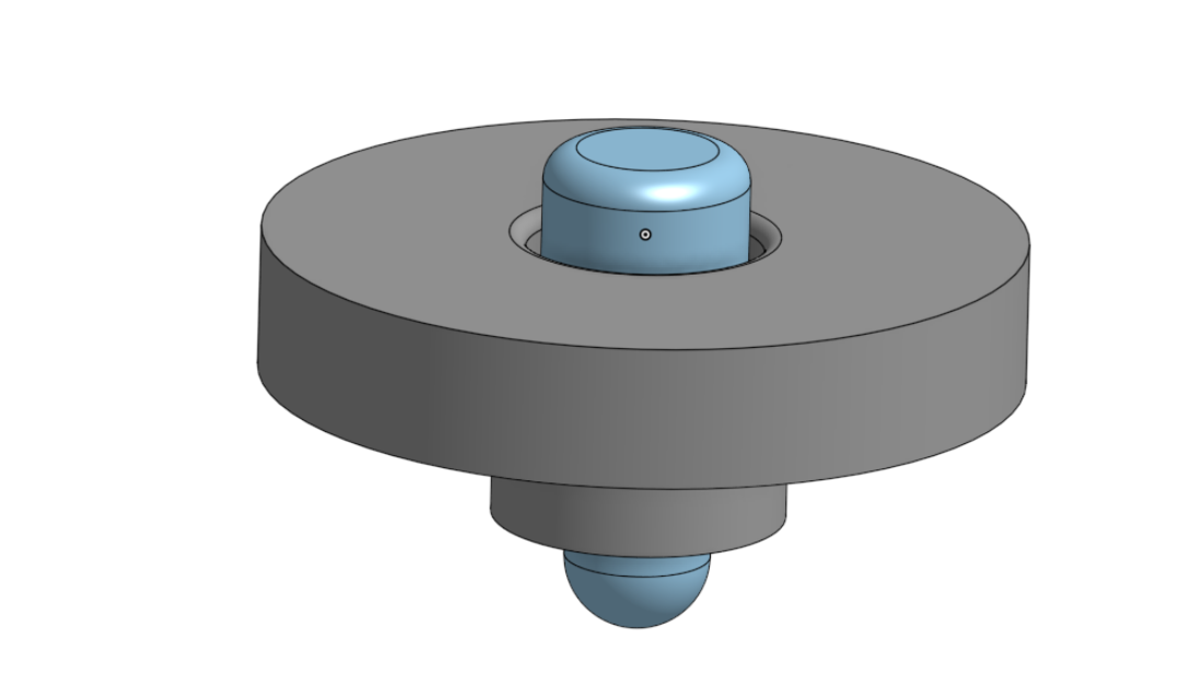
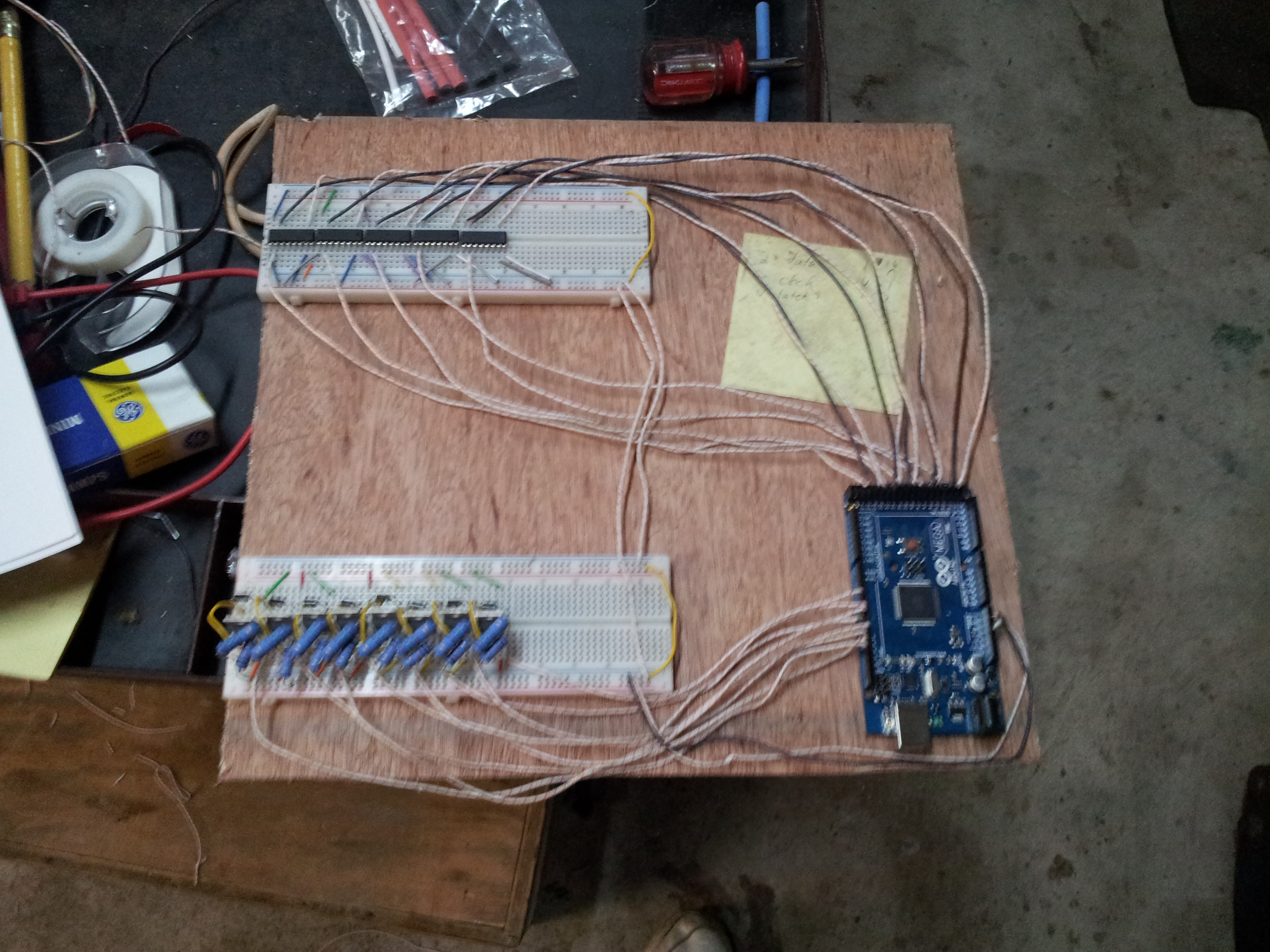
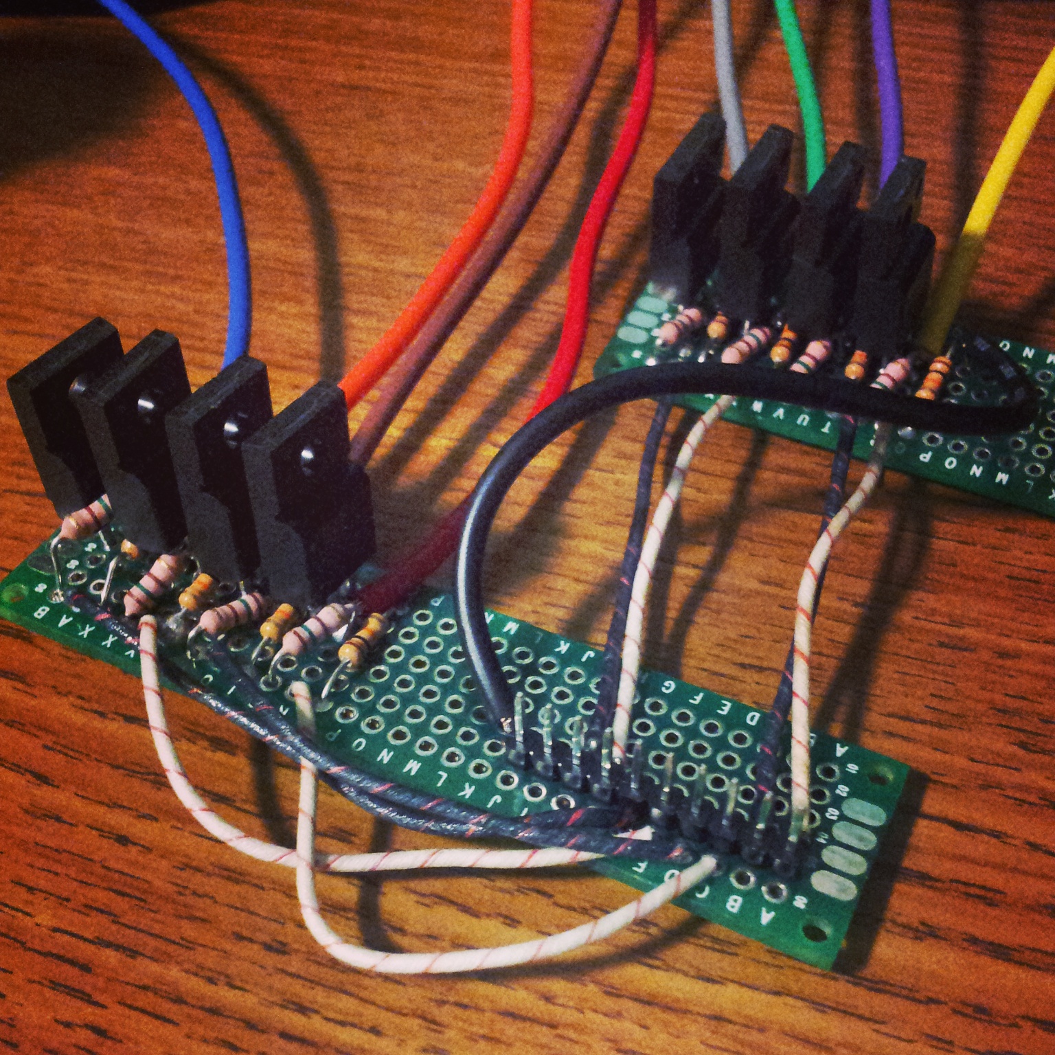
One of the issues I kept running into with the plastic covers was the rollover buttons. My 'free floating' 3d printed ones had ended up working pretty well, but sometimes they'd cause hangups with slow moving balls if the button was also stuck at an angle. In my quest to solve all potential ball trap points, something needed to change. Then someone on the slack channel mentioned these inductive proximity sensors:
Given their side and range, plus the fact that I don't have a wooden playfield in the way, these seemed like a good way to avoid having to deal with sticking the rollovers through the playfield at all. I ordered a few and my initial tests seemed positive. They were easy enough to power from my 12V supply, and just acted like a normal switch once I added a pulldown resistor. The one issue is that I'm using a switch matrix, so I needed some way to interface these 'constant' switches in. I designed yet another little board to go under my playfield which would basically just hook 4 proximity switches into the matrix
I designed some simple 3D printed mounts, and replaced all my rollover buttons
This wasn't quite as well thought out as I'd like, and I had issues fitting them into a few places. I was able to get around that by using some 12mm sensors in a few positions instead of the better range 18mm ones, but the detection of the 12s isn't quite as wide as a star rollover would be. The biggest problem is the rollover in the shooter lane. The 5 bank of drops doesn't leave much room between the rollover and the wall, and the area is just wide enough that the ball can sometimes worm its way past without triggering it. I may have to look into cutting my support rails a bit to make room if this doesn't work out, but I'll see how noticeable it is first. Since I eyeballed the entire cabinet without any planning I've been leaving about 5/8" room on both edges of the bottom of the playfield through the entire length so that nothing could possibly obstruct the support rails, but it could be that this area is far enough forwards that I don't need to worry about it.
Overall these proximity sensors are really cool, and if I'd known about them before I started building my whole playfield might be completely different. I could see myself avoiding rollover lane switches entirely, and maybe some of my hanging gate switches on shots too. The one downside is how tall they are. Compared to the very compact sensors I've seen on the Alien pinball machine, they really obstruct stuff under the playfield, and there's a lot of stuff like mounting them sideways in ball guides and stuff that you could never do. Once I get another shipment of spares in I'm going to chop one open and see if all that size is really needed, or if it's just a big empty cylinder to fit some standard industrial form factor or something...
Cross posted from the original Pinside thread, this is one of many posts regarding my third homebrew pinball machine, creatively nicknamed 'P3'
Having no luck with the flipper resistors, I went to the nuclear option regarding the heat buildup under the playfield, and installed 6 computer fans over all the holes on the cabinet to provide some airflow. Of course, it somehow had zero effect. So, as a last ditch effort, I ordered some PET-G to make a new playfield covering, thinking maybe the acrylic was the issue. To further correct some of the issues with my previous acrylic plastic, I took some rubbings on a large piece of paper and got it scanned at staples.
I'd done similar before with a piece of paper that I'd punched holes in to mark the positions of screws, etc, but some of those were missed or didn't come through well, and I'd also added the holes for all the screens since then, so I needed an update. Based on that, I made an updated CAD file:
Sourcing the PET-G at a reasonable price was a bit of a pain, so I didn't want to waste it. Luckily, I found that I could make serviceable test cuts with my CNC router on plain paper, so I did a few iterations with that to fine tune things. The cuts weren't perfect (rough edges, occasional tears) but it was accurate enough to be useful
Once I was satisfied with all the positioning, I cut the full playfield in PET-G
After reassembling everything again, I did a test game..... and the PET-G buckled just like the acrylic.
So I needed a new approach. Long term the clearest solution here is just to glue everything down, but I don't have any art ready yet and I'm not sure if I could apply and later remove the glue cleanly without damaging the wood. I'd been hoping to eventually cut a new playfield wood with the CNC, but as I continue to have problems with the depth of cut with the PET-G I don't have much confidence in getting that working quickly, so I'm still stuck with my original hand-cut plywood right now.
So I decided to go the other way right now, and instead of attaching everything down even better with glue to prevent the buckling, I decided to just attach as little of it as possible, and make a plastic more like the standard playfield protectors sold for other pins. The new protector would only be held down at three positions (the three posts closest to the center of the playfield), which should keep it from moving, while allowing the plastic to expand/contract as needed to keep from buckling.
Originally I'd rejected this idea when starting to experiment with the plastic covering, as I didn't want the ball to 'sink in' to the empty areas over the screens. But that was also with a thinner material. I'm now using 0.06" plastic, which is much more rigid, and doesn't seem to bend much as it supports a ball over the 9" screen even without being attached down at both sides, so I think it should still play fine.
Now... more test cuts!
Unlike with the full plastic where I only needed to worry about the holes for the screws, here I need to match up to every contour of the ball guides, etc. Which of course I mostly bent by hand/eye and don't have any accurate digital files for. And of course I didn't think to etch them onto the plastic when I got it scanned either. Not a big deal though. I can give even 0.2-0.3" of space around the edges of things safely without affecting the ball (although it looks a bit weird), so I don't need to be super accurate here. And thus, I cut another sheet of PET-G. And also order 2 more spares since I'm now out of stock and I hate to wait for things to ship.
Some things weren't quite as accurate as I thought, but in the end there weren't any major issues. Only two places touched the edges of the plastic, and since it's PET-G it's easy to trim by hand
So now I start reassembling the whole playfield AGAIN to make sure that this still all plays fine. I'm fairly confident this should work though.
Cross posted from the original Pinside thread, this is one of many posts regarding my third homebrew pinball machine, creatively nicknamed 'P3'
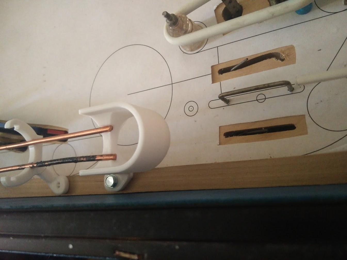
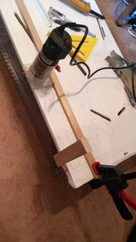
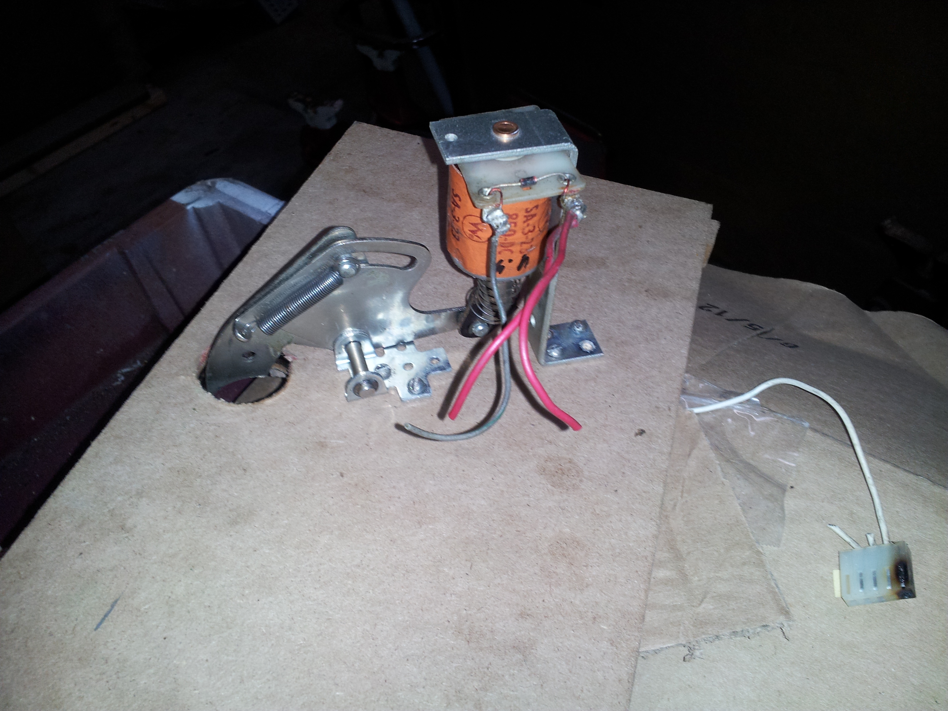
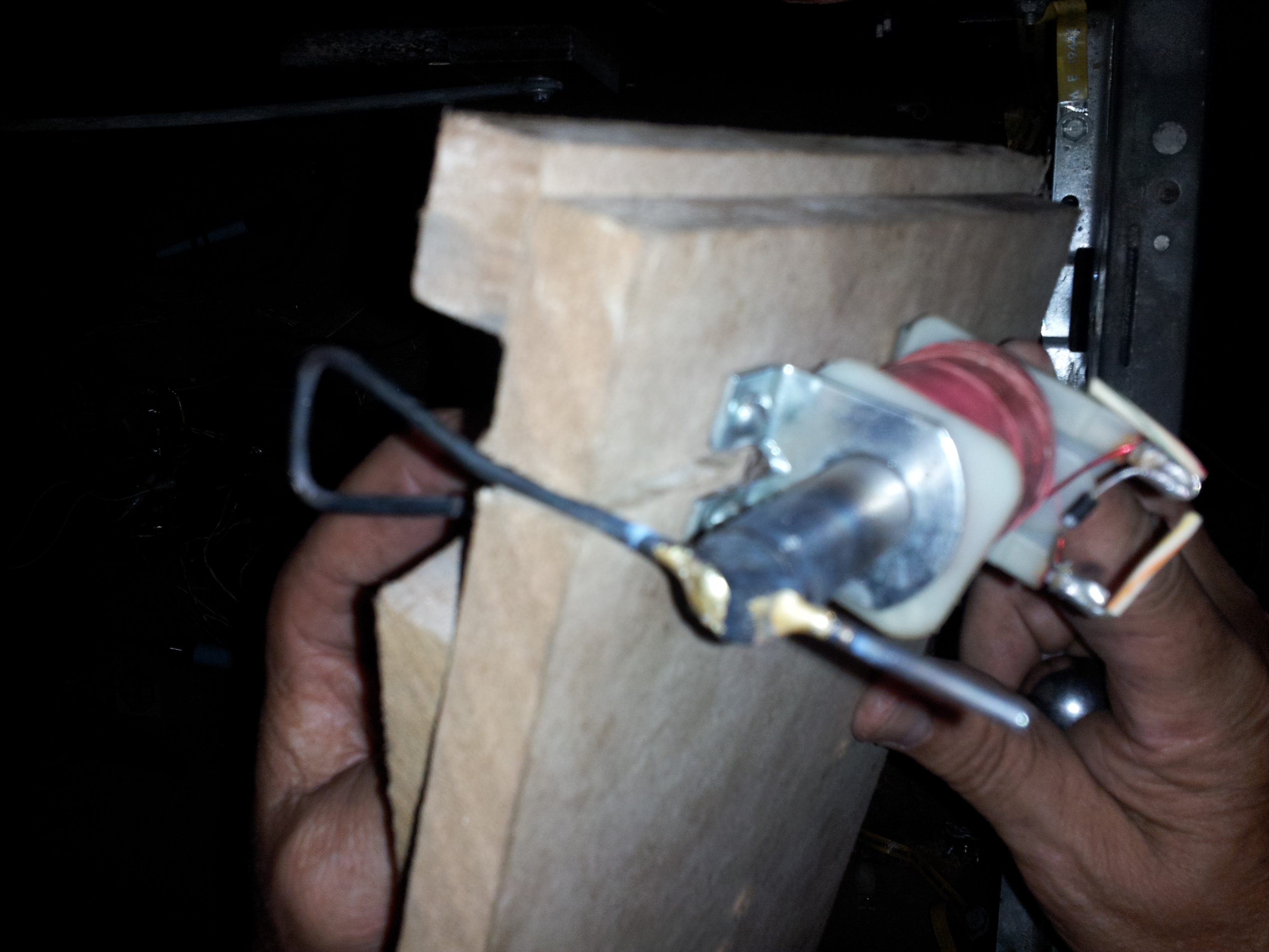
For a long time now I've had my start button doubling as an action button (I disabled restarting a game, and then made the start button trigger the action button code snippet once the ball has been plunged), which has been a bit annoying, and hopefully is part of the reason why playtesters keep forgetting I have an action button (doh!). I've also been stealing a lockdown bar from my Whirlwind whenever I do playtesting because... I don't have a lockdown bar for this game!
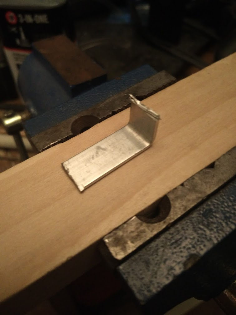
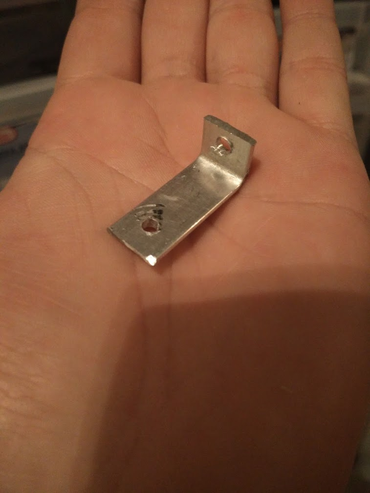
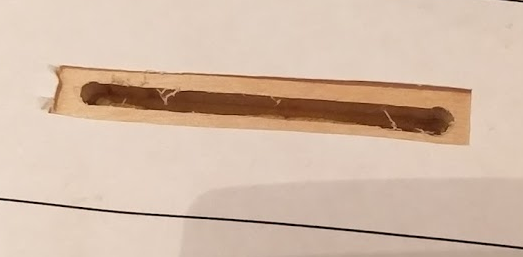
What I did have though is a really rusty spare lockdown bar sitting around. So I sandblasted it, then following McSquid's advice from his Sonic homebrew, drilled a hole in the bar, painted it black, and successfully mounted a flipper button in it using a 3d printed bracket.
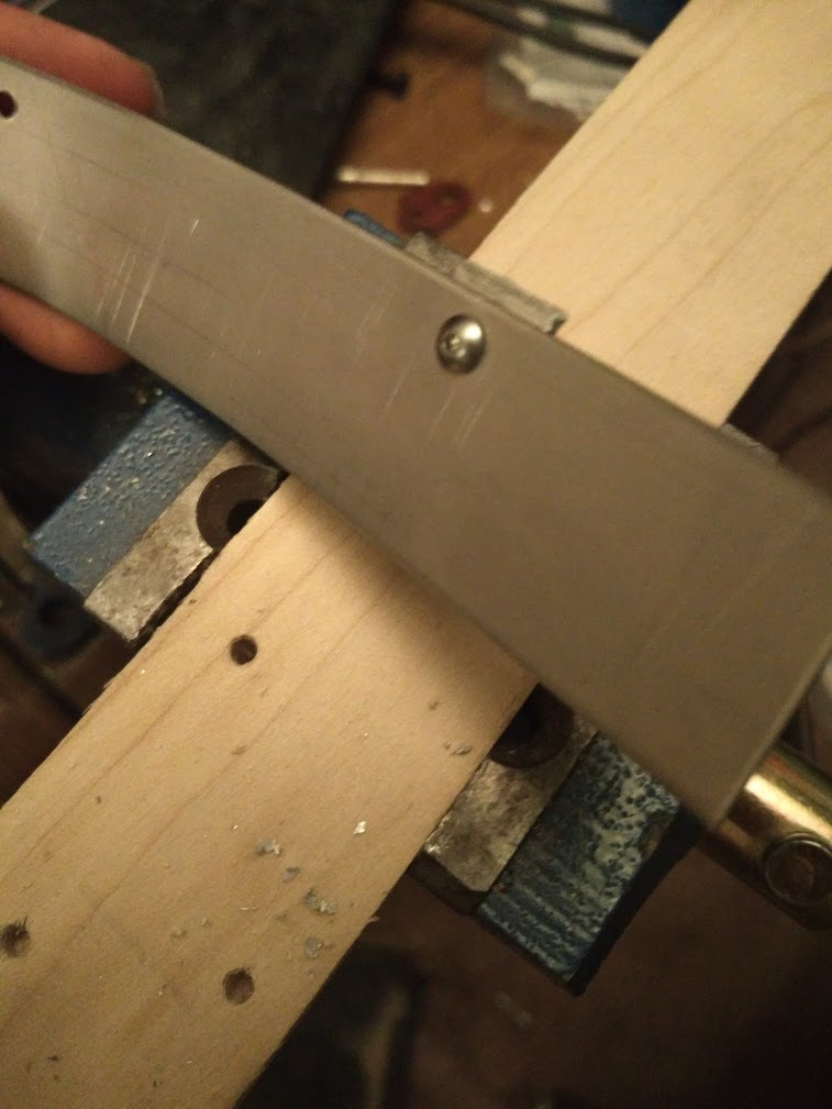
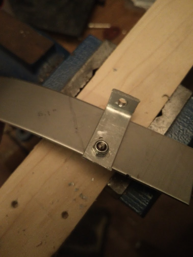
Then I had to get a switch in there!
No problem, just drill two holes in the receiver to mount it, and then squeeze a switch in (with less than 1mm of spare room), snake some wires down, and wire it up. Working good so far, we'll see how it holds up during play
Cross posted from the original Pinside thread, this is one of many posts regarding my third homebrew pinball machine, creatively nicknamed 'P3'
Small updates...
Added a bunch of high scores to the attract mode. Besides stuff like a regular leader board, "best spinner rip", "most hands won", etc I also added a 'lowest scores' board for fun, since technically players can do so bad at poker that they end up in the negative. Could be an interesting thing to compete on!
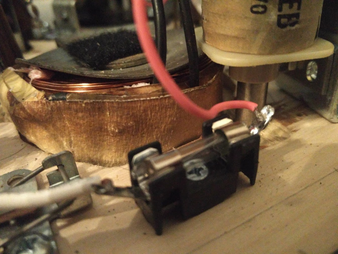
Had another playtester over for a few hours of gameplay. I noticed they weren't really reading some of the mini screens much. Part of that, I think is just because they're generally really weird. It's hard to get used to looking all over the playfield to see what the writing says. But there's a second issue, which is that some screens were just hard to read. Part of this is due to the viewing angle I think. Displays towards the back of the playfield are both farther away and at a more extreme angle, so they lose contrast. Both of those make them harder to read. But the other thing I realized is that my larger rectangular displays were much dimmer than the smaller square displays I was using for the cards themselves. Each of these displays has a BL pin on them, which is supposedly for the backlight, but I was never able to find much documentation about it, so currently I have it disconnected, and the backlight does seem to work. I wondered if maybe the larger displays needed some extra power on that pin or something, so after failing to find any solid info, I gave up and just started sending random signals in to see what happens. It seems like the BL pin is an active low 'disable' pin to turn it off. Not really useful to me. But while trying to find documentation on it, I also saw some places talking about 3.3V vs 5V. Apparently the actual controller chip on these display boards can run off either voltage, and some manufacturers include level shifting chips so either voltage can be used to communicate. But again, I had no documentation for my boards, which I'd sourced from a random shop on ali express from china in bulk. So I figured, only one way to know for sure!, and just hooked one of the displays up to 5V to see if it smoked or not. Luckily it worked fine, AND got brighter! So I had to rewire all my displays get 5V for power instead of 3V :/
Playtesting also revealed a lot of switch issues. My modified small rollover buttons keep getting stuck in a few places, leading to the game going crazy or balls getting stuck, or sometimes just missing switch hits. I'm hopeful that when I get my CNC fixed and cut a new one, I can align these better, but I'm getting really tired of dealing with issues regarding this. Need to come up with a more permanent solution. I've ordered some proximity sensors to play with, and I also have some other ideas regarding the rollover design to play with.
Around the third hour of playtesting, my new thicker acrylic playfield cover started buckling slightly I'm not sure what causes the heat to do this at this point. I left it for like 8 hours plus with the game on, and had no issues, but now after a few hours I'm having issues? My only other thought at this point is that maybe it's the heat of the flipper coils themselves causing the issue. I've noticed that, especially after long games requiring lots of cradling, the lower flipper coils get quite hot and you can smell them sometimes even, despite the EOS being adjusted properly. I think this is due to the capacitor I've added to the power supply to give them more power. I've ordered some high wattage resistors to attempt to wire in series with the hold winding in a way that they'll reduce the strength of the hold circuit (which is already plenty strong) without affecting the power winding. If that doesn't work, then I may have to mount some tiny fans like people are doing on newer games in order to cool them off.
On the subject of heat, I've also gotten some 120mm computer fans to try to get some airflow moving through the whole cabinet. Even if running the electronics minus the flippers isn't enough to affect the playfield, it still does get quite hot in there and I don't like it. I've also realized that my RPi is mounted upside down on my MPU board, which probably isn't helping things. RPi 4s apparently already run hot, and I had installed some aftermarket heat sinks on mine, but a passive heat sink on the CPU doesn't matter that much if it's upside down. So I've designed a new version of the MPU board which will mount above the RPi to fix that. It should also give me enough space to give the RPi a small dedicated cooling fan if needed.
Pintastic New England has announced their next show will be this November, so bringing the game there is my new goal for the machine. I think it's achievable, in some form, but that means it needs to be able to survive a full day of the public playing it without me being around. At a minimum, I need to fix all these ball hangups. That'll mean fixing some switches, tweaking a few areas of the game slightly, and installing plastics and an apron in case of air balls. I also need to get the action button installed on my lockdown bar to get that presentable. If I can get the game bulletproofed, it'd also be really cool to get some cabinet art, but that might be beyond my capabilities right now. Time will tell...
Cross posted from the original Pinside thread, this is one of many posts regarding my third homebrew pinball machine, creatively nicknamed 'P3'
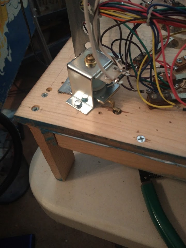
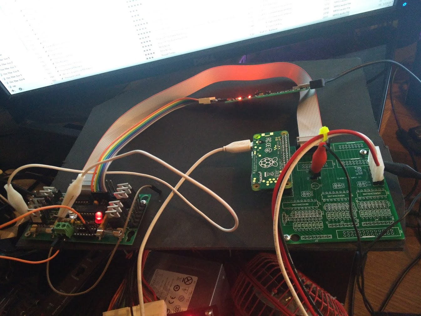
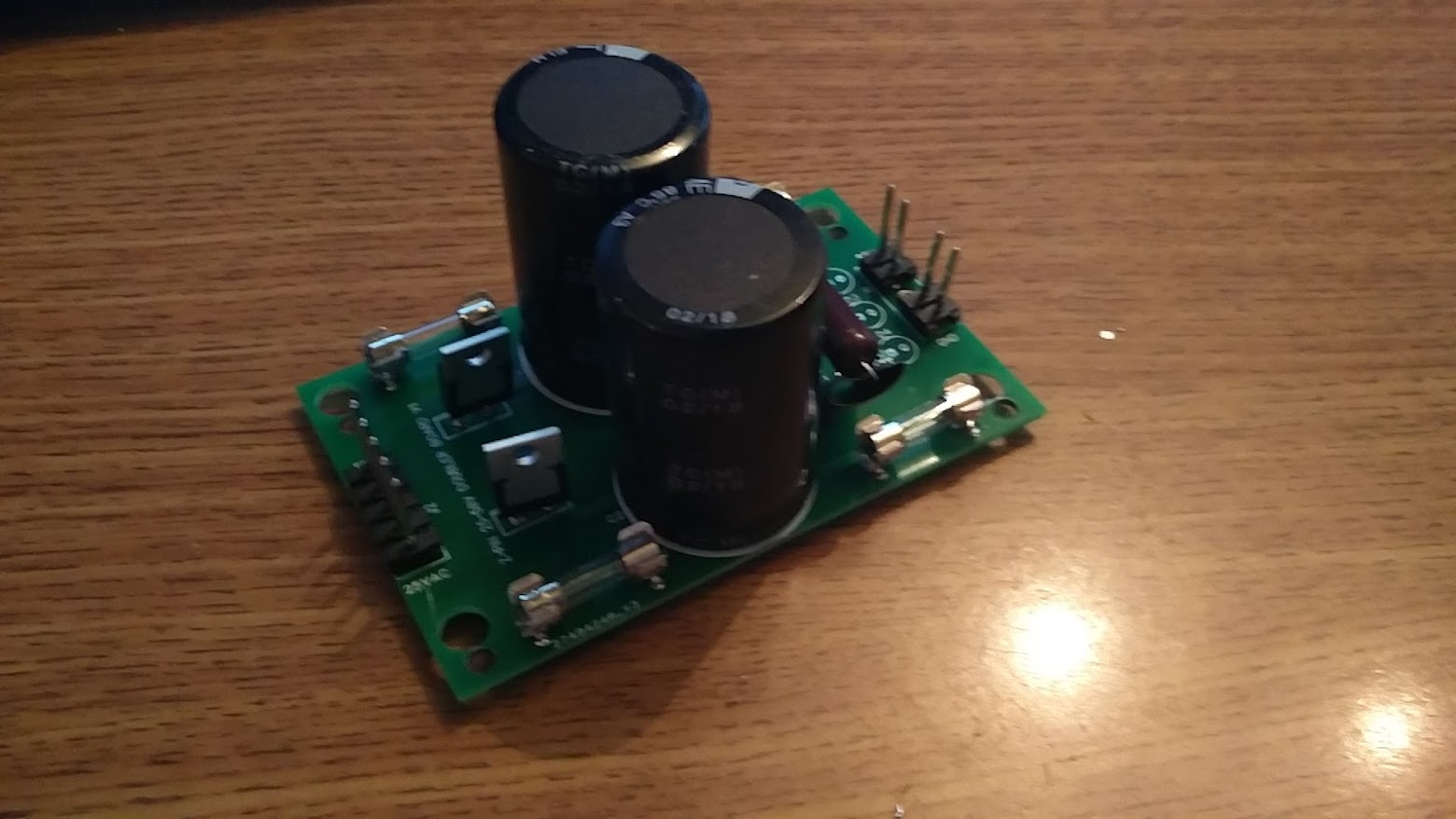
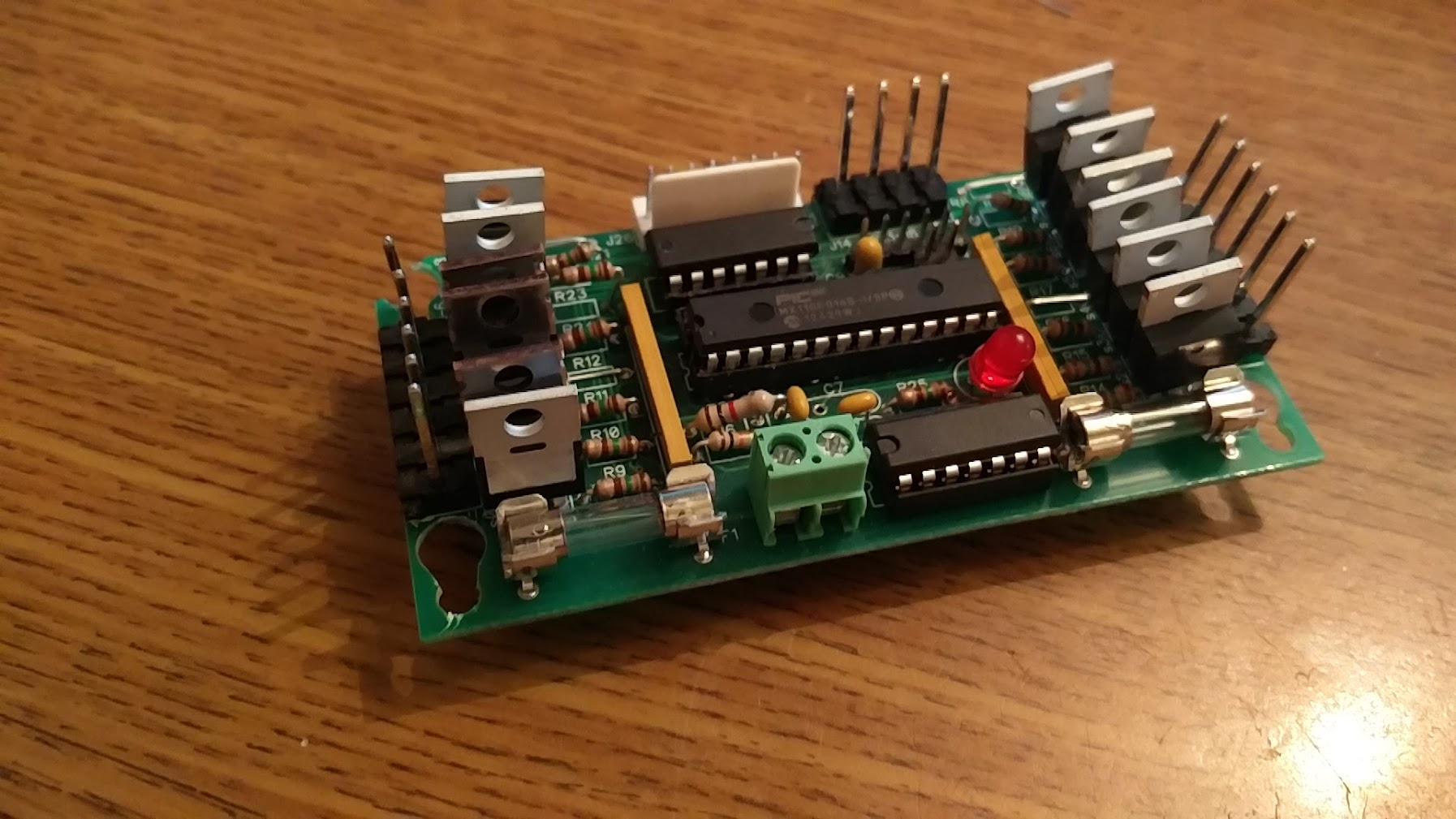
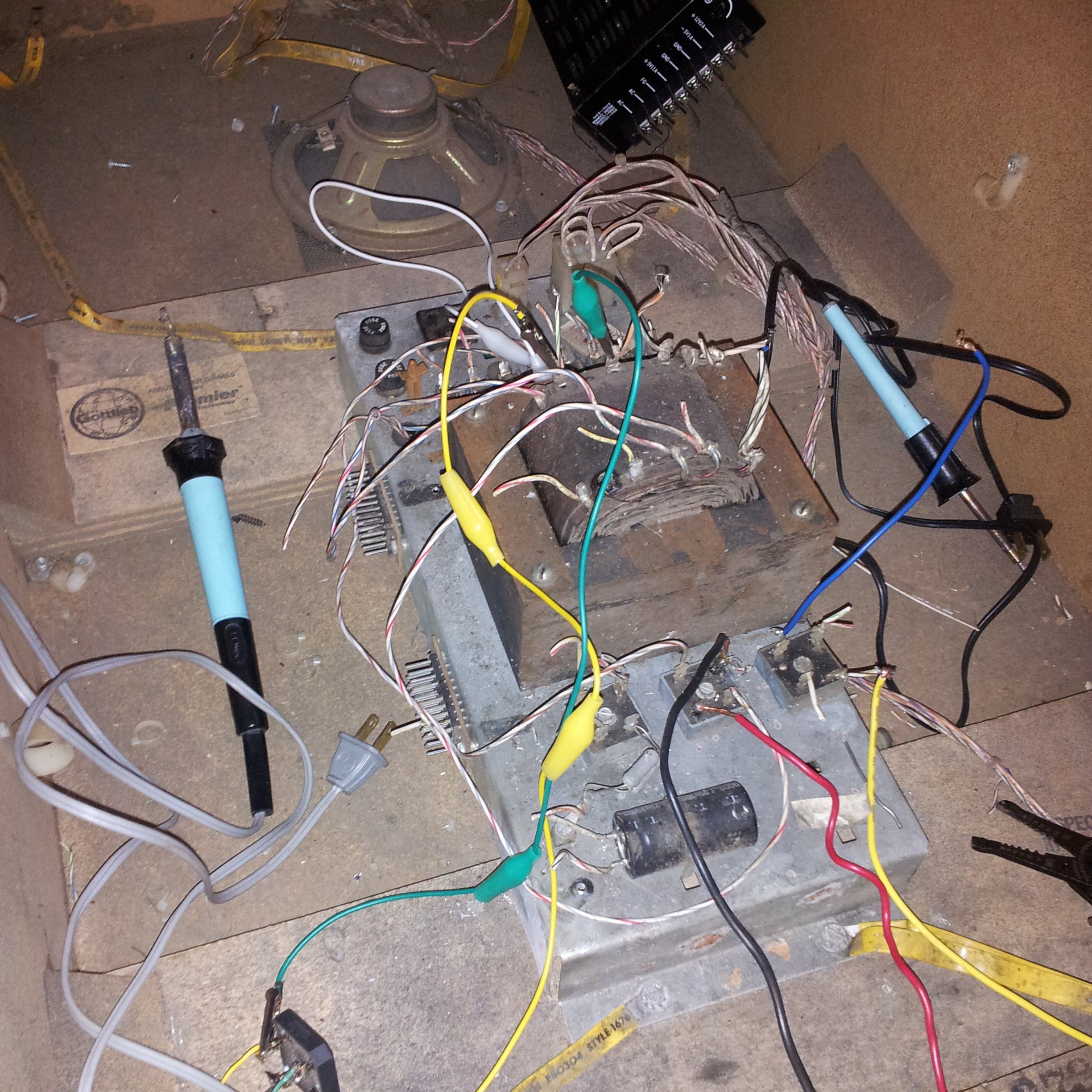
When I started working on this machine, I had a pretty simple power system. 3V for my boards, 5V for the RPi. Both coming from an ATX PSU. 25V for solenoids from an old gottlieb transformer. Power switch turned everything off, as normal, and I added an extra switch inside to cut the high voltage if necessary. A few early mishaps with coils locking on while the playfield was down made me realize the high votlage switch inside wasn't that easy to access, so I added a secondary power switch on the bottom for the high voltage. Very useful, I recommend that for any homebrew... Then I added 12V for the screen. And then 12V for the audio amp. Then another 3V line for the mini displays. And another 5V line for the LEDs. And another 5V line for the second RPi to power the mini displays. And another 12V line for the light strips. Each of these had its own fuse, etc, all coming from the ATX PSU. Luckily I designed a power splitter for the ATX-24 connector that could support all that, which has somehow managed to be future proof enough to keep me going and keep everything vaguely organized. Then I had to move each Pi to its own separate supply, due to noise issues coming into the amp.
However, there's a problem with that. I have three separate processes across my two Pis that currently need to be manually started, as I haven't made them automatic yet, and they sometimes need some massaging. My Pi also has a weird issue where about 1/4 times you power it on the OpenGL drivers just... won't work. I can't find any solution for it, so my only real option is to just repeatedly reboot the Pi and restart the processes until they work. Plus I have another weird issue that I've never been able to track down where the Pi won't boot if the cabinet switch matrix returns are connected. Can't figure out what could be causing that, and I'm hoping that a new MPU board revision will magically fix it. But in the meantime it means that, when I turn the machine on, I need to first reach in and unplug a connector, wait 5 seconds, then plug it back in. Then I walk over to my computer, SSH in, start all my code. If the driver is dead, I need to reboot, then pull the connector again. Sometimes this can end up being a 5-10 minute ordeal. My solution? Just don't turn the game off! So instead I reach in and unplug the LED power supply, light strip power supply, and mini display power supply. Then I grope around and find the power button on my screen and turn it off, and then I reach under and kill the high voltage. Game now appears 'off', but the Pis are still running. Easier, but it still leaves me in a situation where sometimes I avoid playtesting my own game because it's too much of a pain to turn on! So that had to stop. I realized that, in the end, all the systems I want to turn off are coming through the ATX supply, and my Pis are on their own supplies, so really I just need to turn the ATX off. If I'd planned this from the beginning I probably would just install a third power switch, but I don't feel like taking everything apart again to do that. So instead, I replaced my internal HV switch (which I never use anymore) with two extra 'service' outlets, and plugged the Pis directly into them. So now the Pis are just 'always on' as long as the game is plugged in, which is fine with me. Meanwhile I have a primary power switch which kills everything in the game except the Pis, and an extra switch to turn the HV off if needed. Much better
Cross posted from the original Pinside thread, this is one of many posts regarding my third homebrew pinball machine, creatively nicknamed 'P3'
In between these playfield changes I've been making a bunch of tweaks to the code. I added another multiball, rounding out the main hands (straight, flush, and full house). Added a mystery award which is really fun but hard to explain via text. Lots of tweaks and bug fixes. But mainly I've been working on sound!
The game now has more than 100 sound effects and callouts (and still many to go). At first I was agonizing over trying to find some good sounds that fit everything well, etc, but I've realized that you don't need a 10/10 sound effect to add quality to the game. Even a 5/10 sound effect is way better than no sound effect, as long as you've got them everywhere. Sadly I've also realized that making 5/10 sound effects is way harder than I'd have guessed. I've spent a bunch of time with a mic, a few poker chips, and a deck of cards, making random sounds by hitting them against each other, etc, trying to get some good, real, 'poker' sounds to put in.
On the software side, I did some research into how other games handle sounds. Playing one sound is simple enough, but it seemed like if I just played every sound that came in (and every call out, etc) things would get messy. You never want two callouts at once, and I figured you may not want multiple sounds at once either, so there needs to be some system in place for that. Sadly, it turns out that getting Java to play a sound, and then kill that sound mid way, adjust volume on the fly, or even just get the length of the sound are all more complicated than you'd expect. I ended up writing a custom mixer to combine a music channel, a voice channel, and a few sound effects channels together on the fly, which gave me the level of control I wanted. Currently I've got a simple system set up where, if a sound is playing on a channel, nothing will interrupt it (after like 50ms). If you try to play a sound but there's already another one going, that new sound is ignored. If two sounds come in at once (which happens a lot since I might have the base game make one sound effect, but then the mode you're in at the time makes another), I just choose the longer one. Originally that was a hack until I could code some proper 'priority' system in to let me manually order the sounds but so far it's worked surprisingly well so I haven't had the need to go further. I've also implemented some ducking, so the music and effects will get quieter when there's voice playing, and the music will get quieter when there's effects playing. Took a bit of play to get that to sound natural, but once it did it worked well.
Cross posted from the original Pinside thread, this is one of many posts regarding my third homebrew pinball machine, creatively nicknamed 'P3'
Sometimes to get an idea as you fall asleep saturday night.... and then spend your sunday making it work
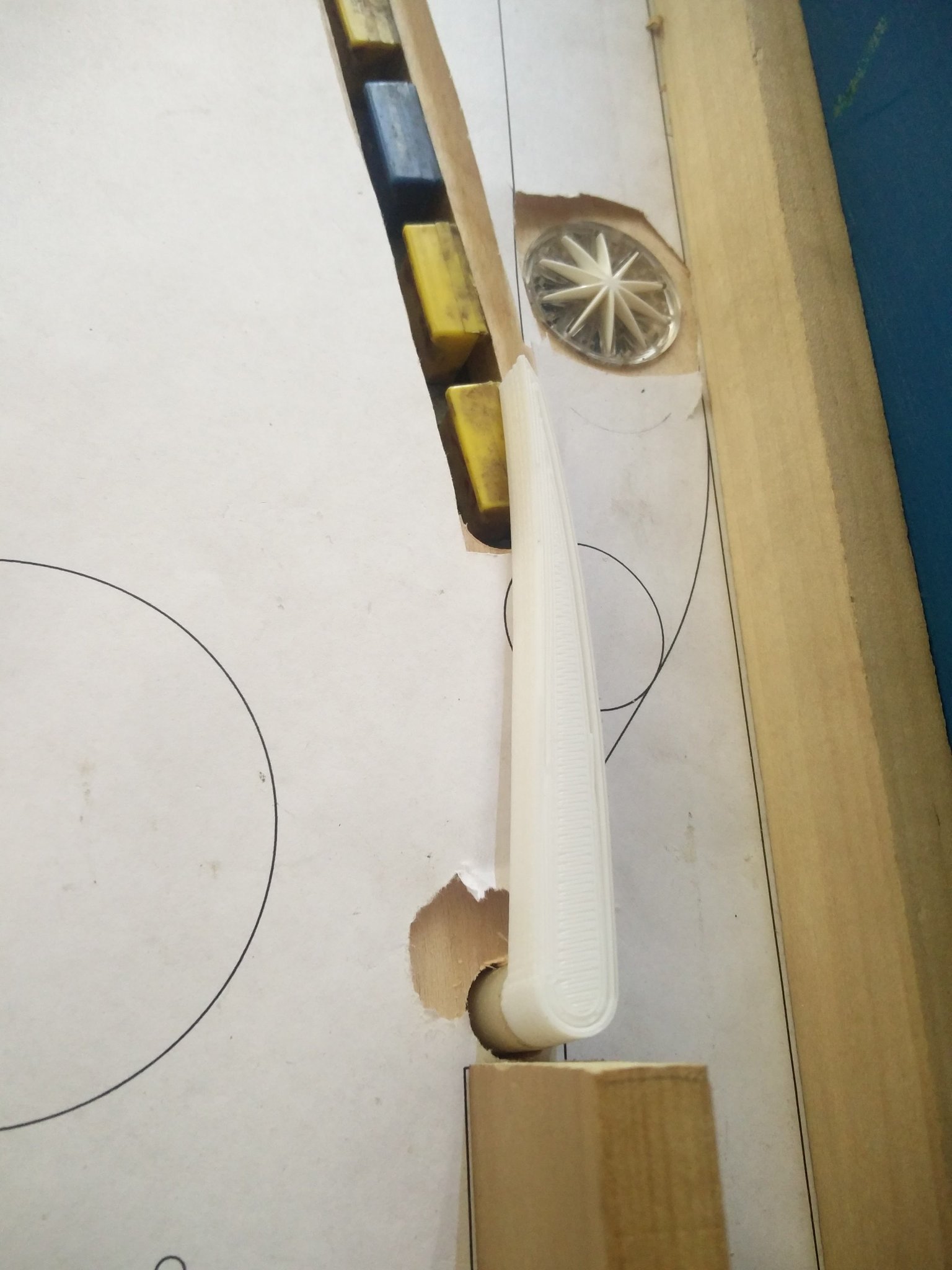
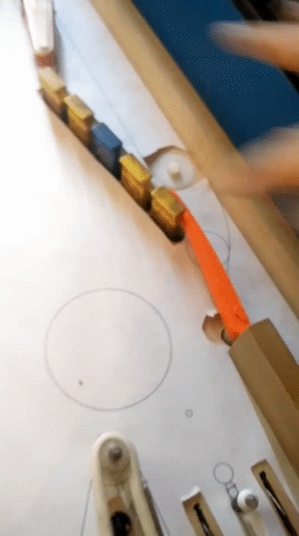
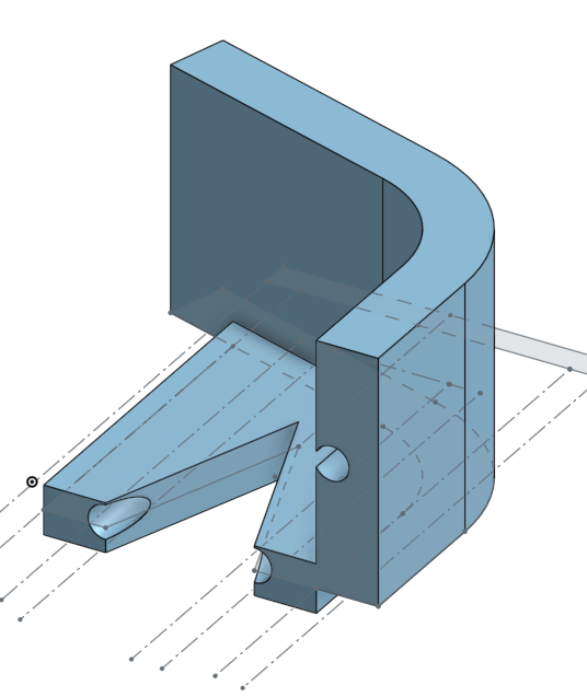
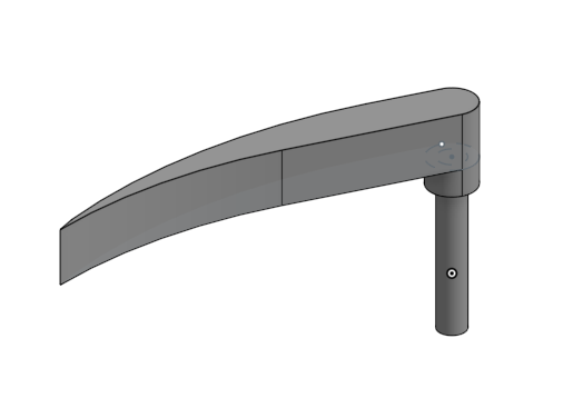
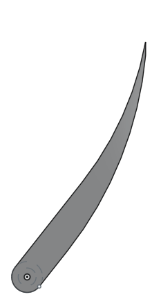
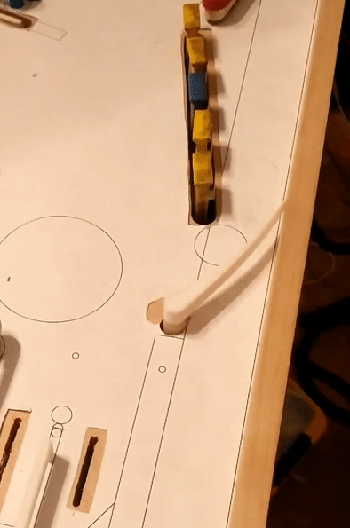
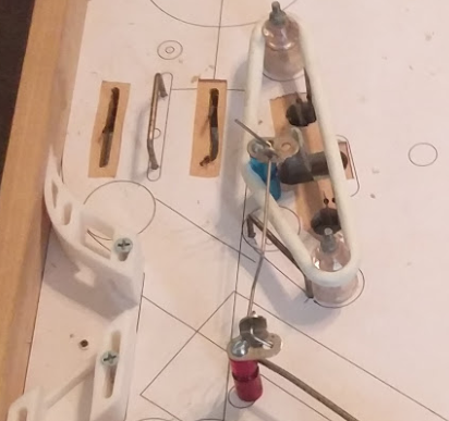
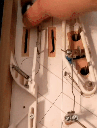
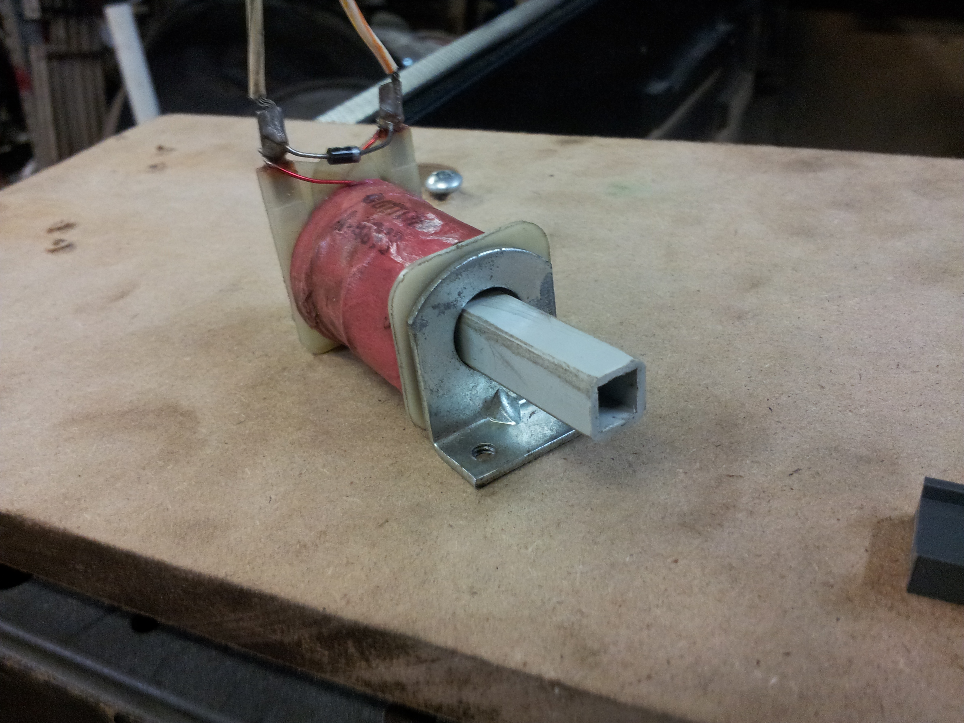
My upper magnet has never worked how I wanted. My goal was basically just to be able to shoot the left orbit and feed the upper right flipper. Magnet couldn't grab the ball. So I added the up post. That wasn't 100% reliable at even catching the ball, and when it did, the magnet still couldn't grab it somehow. So I cut the hole all the way through the playfield to give the magnet more power. Didn't help at all. When I made the new plastic playfield, I didn't even bother cutting a hole for the up-post. My thought was, instead of shooting the left orbit to feed the magnet, I should be able to shoot the spinner, and use the spinner to activate the magnet, since the ball would basically be in perfect position over the magnet when the spinner switch closed. But that, of course, didn't work at all. Magnets suck! I ripped out the magnet. Maybe I should just forget this entire idea about feeding the upper flipper. I basically only ever used it for one of my four multiballs which had a jackpot only hittable from the upper right flipper; it seems like a waste to put a whole mech in just for that. But the multiball was based entirely around that upper flipper shot (it's basically a lawlor throwback themed multiball), so I'd have to rewrite that whole multiball somehow. Plus then I'd have no need for the target under the upper left flipper which I've gone to a lot of pains to implement. There'd barely be any reason to have the upper flipper at that point; all it'd be useful for is trying to feed back to the upper playfield area if you drained out of it to the right.
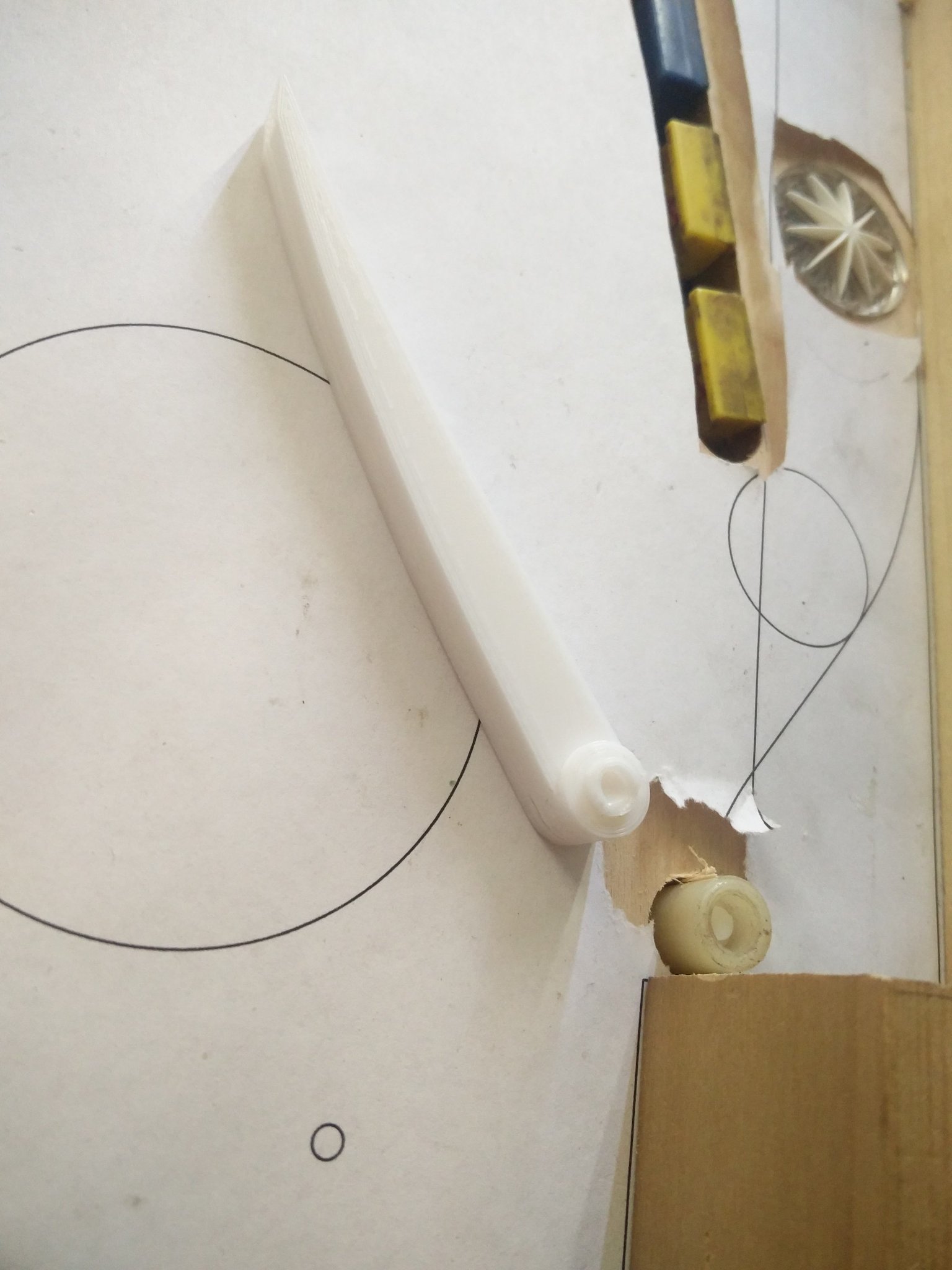
So I needed some other way to feed the upper flipper. Before, on the left orbit, approach, I'd tried to figure out how to work a diverter in there, but there just wasn't room any way I could find. While watching the magnet fail to catch the ball via the spinner shot I thought, it'd be cool if I could like, have a raise-up captive ball. I've always liked how captive balls feed flippers but you don't see them in too many games. But there was no room in front of the spinner to try to make something like that due to the screen+lights. And I couldn't really put it behind the spinner since I had a giant hole there from the magnet and you wouldn't be able to see the captive ball well to aim for it. But I figured you don't really need a captive ball at all. Really you just need a wall for the ball to hit to fall back to the upper flipper. A single drop target that could raise up would be cool, but I think the rebound would be too fast. I really just want to deaden the ball and let it gravity feed for the shot to be makable.
Thus:
In the up position, the ball goes underneath just like normal. When it's down it sorta catches the ball and lets it fall back down again. It isn't always a perfect feed but you can always get a flip at it
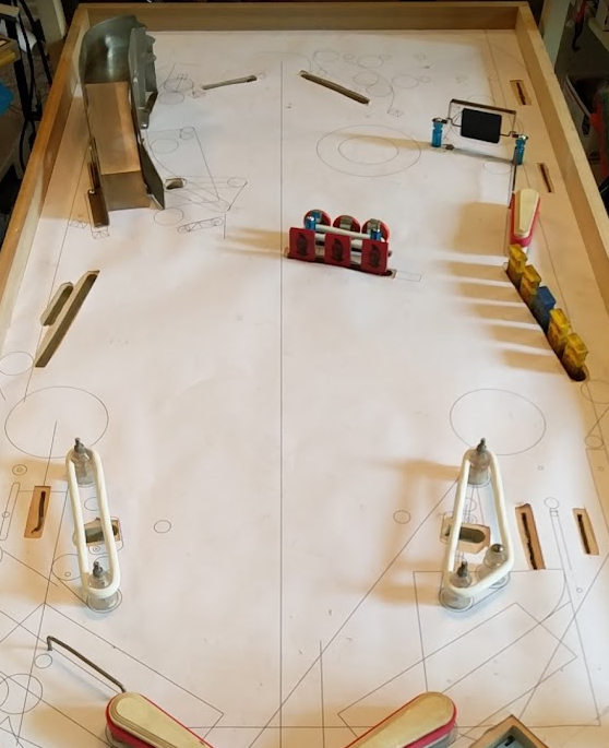
Cross posted from the original Pinside thread, this is one of many posts regarding my third homebrew pinball machine, creatively nicknamed 'P3'
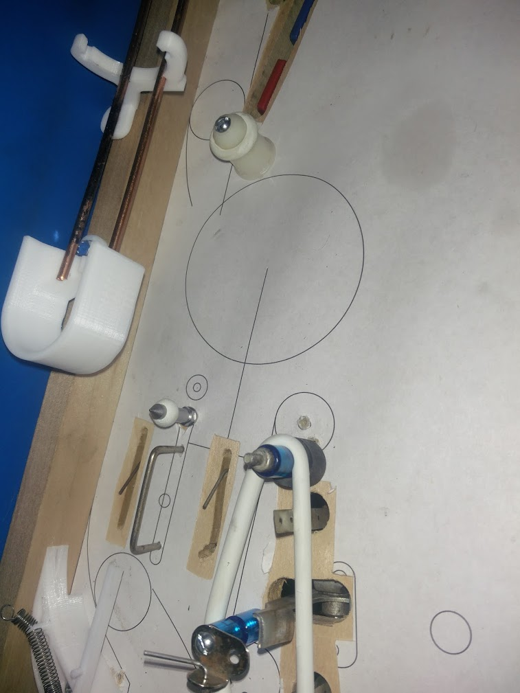
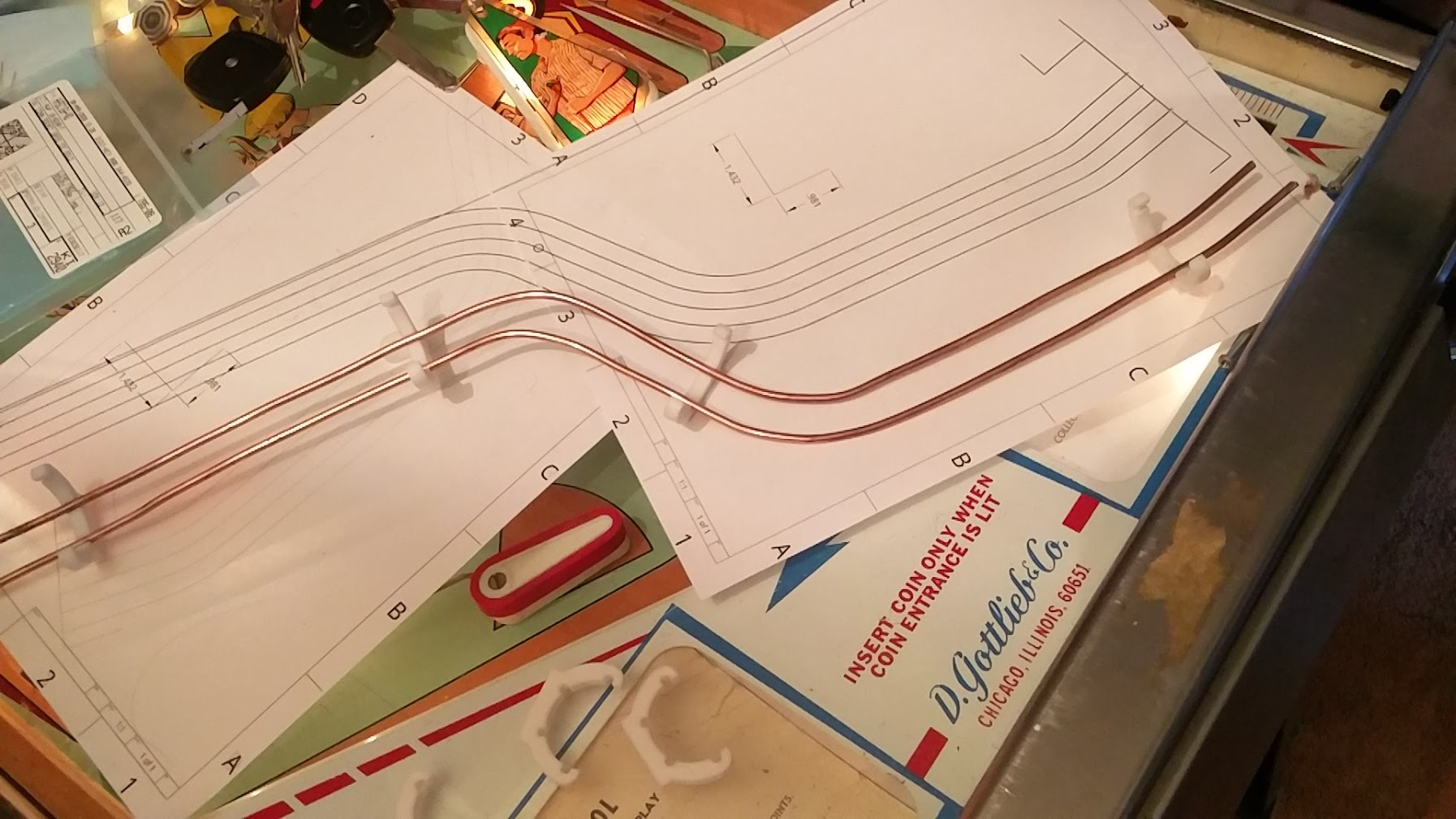
I'd been considering something similar, and then I saw these on the Sonic Spinball homebrew and got a link to the strips, so I added some light strips along the sides for GI. Actual GI bulbs had never really been in the plan, since they'd need to squeeze into some tight spots. Plus there aren't that many spots to put them, which confused me a bit at first. When you look at the playfield though, other than the slingshots and around the ramp, there's pretty much no spaces where a GI bulb could even go. When designing I like to make the most of the space, but maybe it's a bit too far?
I got some plain warm white LED strips, and some V channel guides for them:
Then I 3D printed some supports for them that stick into the triangular hole in the back of the channels
I mounted them onto the side rails, instead of to the cabinet like Sonic + Pinstadiums do, so there's no need to remove them when lifting the playfield. They sit about a millimeter below the glass
The illumination doesn't cover the whole playfield quite as nicely as I'd like, but if I wanted anything else I think I'd need to custom design some channels to aim them at like a 30 degree angle instead of the 45 or 0 angles commercially available.
If I'd planned these from the beginning, I might have made some custom metal channels, with some stronger metal mounting posts, so that I could actually set the playfield upside down on them for servicing (and maybe some spare attachments at the front to make it even). I like the idea of the playfield having complete protection when removed from the cab. I've got the support rails on the bottom covering that side, so I can easily pull the playfield out, set it down on a table or on end, and not worry about the mechs, but currently if I want to set it upside down I need to use the wooden back wall and manually install some more wood posts to the hangers in the front, which isn't too convenient.
I'm not sure if that'd be worth the effort though, and I'm not sure how satisfied I am with this technique. For a whitewood like this that I've been winging the design on a bit, they're really nice. No need to make concessions for them in your plans or worry about wiring, etc, but they also have an annoying glare on the playfield. It's especially noticeable here since I have a perfectly flat acrylic sheet on the playfield, while a clearcoat would probably be a bit more subdued. The glare isn't in the main play areas, so it's not a deal breaker (they're better than no lighting!), but I'll have to think more about other options or tweaks to this in the future
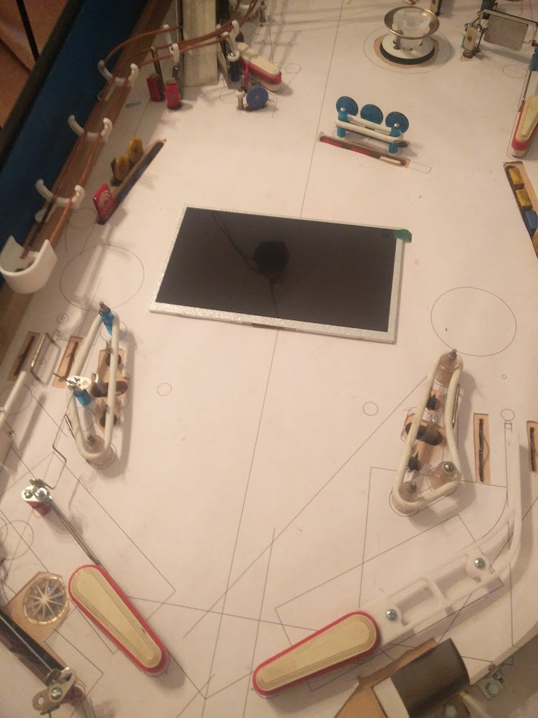
While the coverage isn't completely even, these new lights do illuminate the back wall (or lack thereof!) though, so I'll need to think about that more at some point. Technically you could airball right over the back wall and into the cab currently, but I've never seen that happen. It also illuminates that there's a ton of dust on my playfield :/ Sadly that's what happens when your game sits for months with no glass on it, and I don't think that'll be changing any time soon. I may need to station a shop vac nearby for convenience though.... There's still a lot of ball hangups, etc currently so I couldn't really have the glass on for too long anyway. Actually I don't even have a sheet of glass for it since I stole it for another game to replace some non-tempered stuff; and I don't have a lockdown bar for it either. At some point I'm going to need to put a focus on getting some glass, getting a bar, installing an action button, and then dealing with all the stuff that keeps me taking the glass off: I'll need to make some plastics (easy, but may need to swap some posts to mount them), add some more stuff to prevent airballs from getting stuck places, make an apron of some kind, etc.
Cross posted from the original Pinside thread, this is one of many posts regarding my third homebrew pinball machine, creatively nicknamed 'P3'
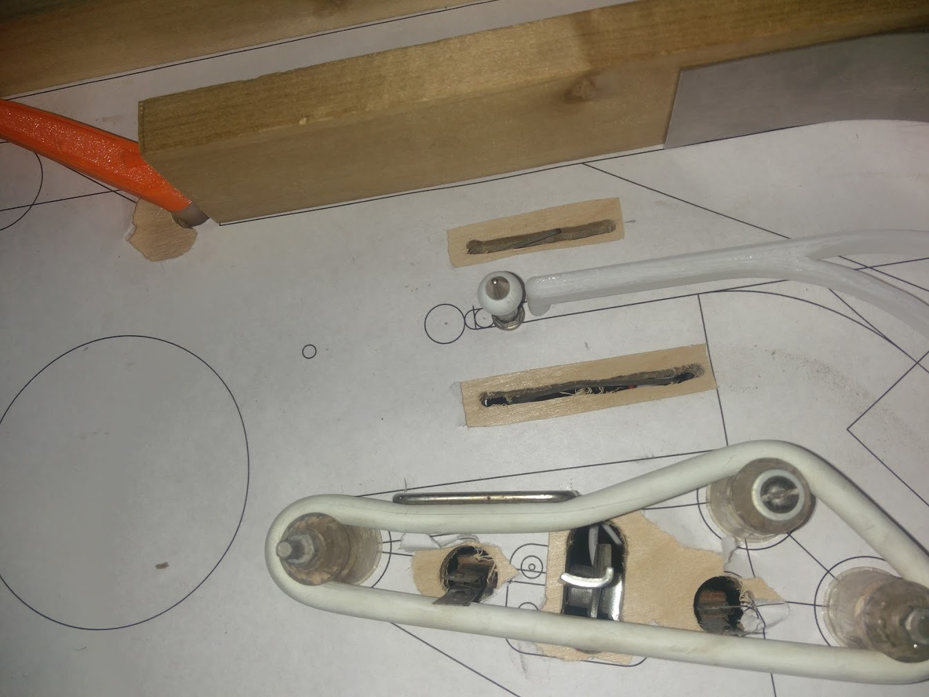
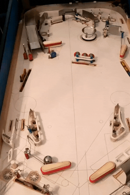
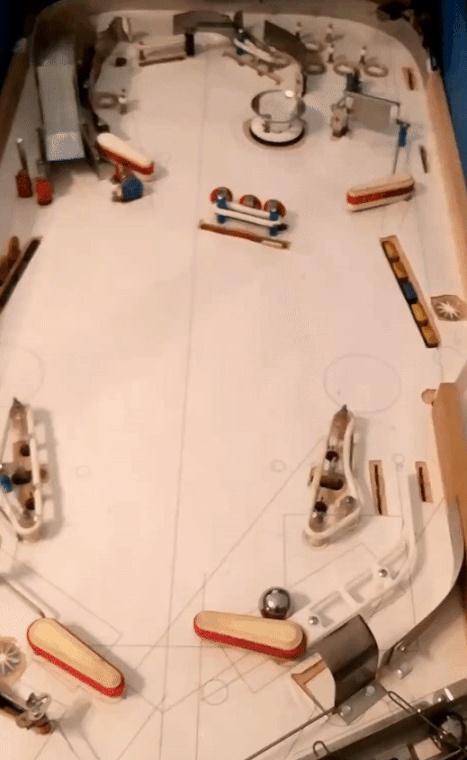
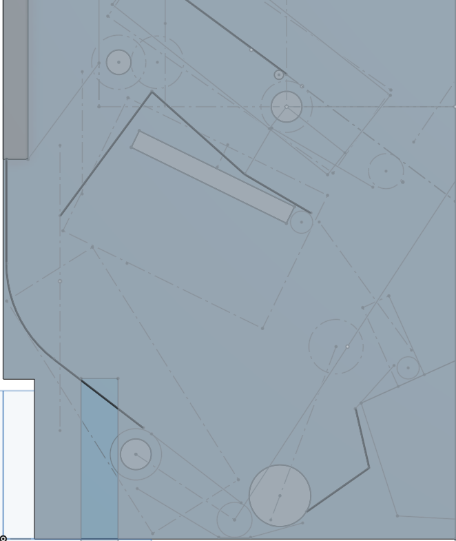
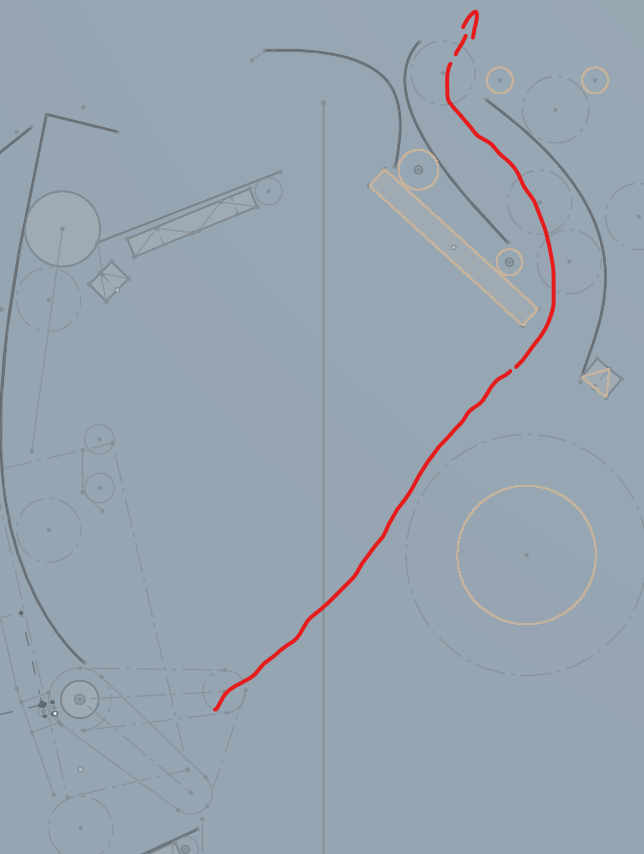
While I had the playfield apart, I also made a few layout tweaks
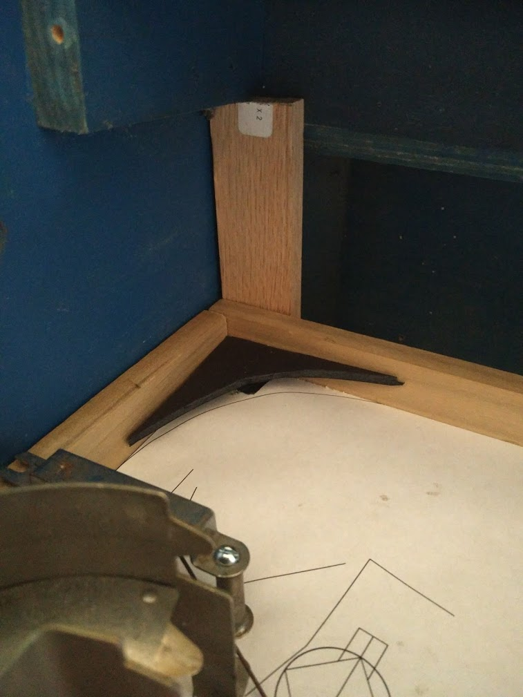
This is the guide for the upper left flipper. Old guide on the bottom. It had a split in it for a standup, but it turns out the flipper can't hit that angle. No matter how I aligned the eject plunger, I couldn't get a clean feed past that gap. So I made a new, one piece guide and installed it. Now the ball comes down nice and smooth to the flipper. Almost too fast, to be honest. I need to play with that mech a bit, see if I can get it to give a slower kick.
A bit hard to see here, but I added slots for adjusting the height of the left outlane posts. Eventually I'd like these to be slots in the wood too, with machine screw posts, so they can be precision adjusted, but right now the area underneath is too messy to safely install that.
The center post on the right side got a horizontal cut, since it can't really be moved vertically due to the feed from the shooter lane. Also replaced the upper end of the shooter/outlane divider rail with two mini posts. I'm not sure how that will affect the play in that area, but hopefully it does something. Previously it didn't seem like there was much to 'do' over there. You'd just watch the ball balance on the center post and fall one way or another, and any ball hitting the wood rail would just die and go down the outlane. So I'll see how this goes.
Cross posted from the original Pinside thread, this is one of many posts regarding my third homebrew pinball machine, creatively nicknamed 'P3'
Finally got the lights all working, and coded a simple attract mode animation for them. Originally I was trying to use an existing server I found for controlling ws2812 leds, but it kept crashing and wasn't very suited for pinball animations, so I coded a simple server myself which just handles a light being on, flashing, or pulsing, with settings for frequency and phase. I think I will need to tweak my colors a bit though. Not sure if it's because of the specific leds I got, or the way the opaque white inserts are coloring it, but everything feels a bit 'pastel'...
The downside to doing all your leds as one giant strip, I guess, is that if you want to change them later it's more complicated. And of course, once I got everything together here, I realized I'd forgotten to install a light for the lower playfield diverter. So I guess at some point I'll need to cut a bit from my left over led strip, attach that there, then cut my existing strip somewhere, and run the data line over to the new led and back again.
I'm also thinking about maybe having a sort of 'wizard mode' accessible after you get all the main hands (at least straight, flush, full house, since technically those cover all the 'lower' hands too. maybe four of a kind, but it's hard to guarantee there's ever a deal with 4 of the same card), so it'd be nice to have a few more inserts in the barren center area between the screen+slings for that. Just when I thought I had all the lights/etc figured out!
Cross posted from the original Pinside thread, this is one of many posts regarding my third homebrew pinball machine, creatively nicknamed 'P3'
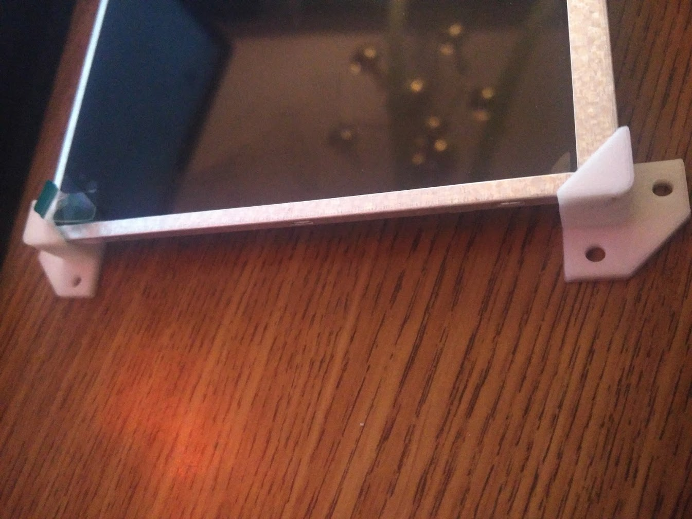
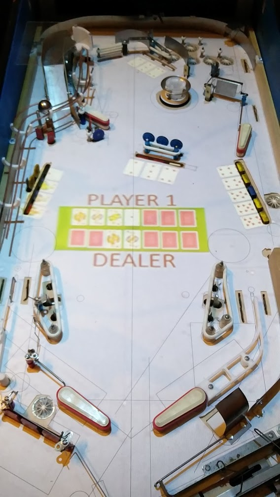
I'd been getting tired of using the projector for everything, and with the lights taking away half of its use, I figured it was a good time to get to work on the other part of that: the cards themselves. I'd realized early on that having all the cards just printed on the playfield, unchangeable, would have a possibility for people finding certain cards to go for every time which would make the game less fun, and having the projector able to deal a random set of cards onto the playfield solidified that worry. And then I found some cheap LCD displays on ali express while searching for the main screen I installed before
Turns out they were slightly narrower than the spacing on the drop targets:
Thanks to the provided example code it wasn't very hard to get one to display a card using a raspberry pi
But could you drive more than one easily? I made a little board that had a shift register on it to control the CS line of the display, so that I could theoretically wire up to 8 displays to it
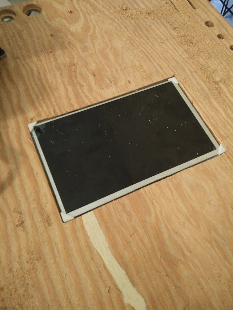
So far so good! Now, could I fit those displays in front of the targets? I did some measurements of the 3 bank in the middle and printed a bracket
And they fit! barely.
I programmed a simple tcp server to control them, and hooked the 3 displays into the game
Alright, proof of concept complete. Time to go way too far with this.
I'll need to custom make a bracket for every bank in the game, since they're all different manufacturers+sizes
And since I'm already getting into this, why not throw some other single displays around the playfield?
Now, can I actually drive them all? No. I lose signal around the fourth board. A lot of learning about signal integrity and I've got another version of my board with some termination resistors and a buffer chip to redrive the signal between each board
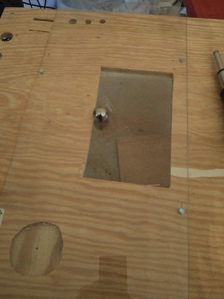
And with that, I can barely get all my displays to work
So I cross my fingers and cut a lot of big holes in my playfield. The amount of missing wood at this point is starting to concern me a bit, but it seems to hold up okay when the side rails are attached.
Wiring them up is also fun. So many ribbon cables! Almost looks like a Spooky game...
And once I finally got the whole playfield reassembed...
Success!
Cross posted from the original Pinside thread, this is one of many posts regarding my third homebrew pinball machine, creatively nicknamed 'P3'
Still working on a bunch of stuff so I don't actually have any top side pictures yet but..... light!
The funny side effect of just trailing a light strip around the playfield is actually looks cool underneath too.
I ended up using 126 LEDs worth of 30/m strip to reach all ~30 inserts on the playfield. Besides from a few places where I didn't plan for lights and had too many mechs in the way, it was pretty easy to mount the strip over the the holes. The budget pack of clips I found are a bit too big, so there's still a bit of back and forth play, but I don't think there'll be enough movement to cause any issues.
I hooked the strip up to a dedicated 5v line+fuse coming from my ATX PSU, and it seems to be lighting fine with just that power coming in at one end (I was sorta expecting needing to provide more power somewhere along the length), even with all the lights on (which will never happen in practice). I had to make another little adapter board for my RPi-powered MPU to add in a 3V - 5V level shifter since the RPi only puts out 3V, but that seems to be fine for driving the whole strip, with an added 4ft of wire between the board and the beginning of the strip. Time will tell whether the electrical noise interferes with the lights once everything is playing, but hopefully they'll be okay (plus I plan to refresh them at 30Hz so any glitches should clear up quick).
Cross posted from the original Pinside thread, this is one of many posts regarding my third homebrew pinball machine, creatively nicknamed 'P3'
Got the inserts from PBR, luckily they're the same size I was planning on, so I went ahead and cut all the arrows.
Midway through I stumbled upon this technique, drilling three holes through first, then routing out the rest using the guide, which allows me to do all the routing in one pass (before it was three passes since I kept needing to stop and remove all the dust, etc). Then once it was cut and the insert test-fitted, I'd take the guide away and hand route between the three holes to leave a good open area in the center for the light.
I was hoping that the circular inserts would match up with my forstner bits, but not all of them did. The smallest one (5/8?) are perfect, a nice snug fit, but the 3/4" are just loose enough that they'll fall out from gravity if there's any vibration. I'd like to get these all press-fit if possible so I don't have to worry about gluing them, so I'm going to try to make another router guide for the 3/4"
Cross posted from the original Pinside thread, this is one of many posts regarding my third homebrew pinball machine, creatively nicknamed 'P3'
Got the LED strip today. Was surprisingly easy to get working using adafruit's python library, worked the first time. Sadly I don't want to use the python library so I'll need to explore alternatives for integrating it with the rest of the code. I did some experiments with inserts. The circular ones lit up fine, but the larger ones like the arrows had a bit of coverage issues.
It's hard to get good pictures of leds lit up, but
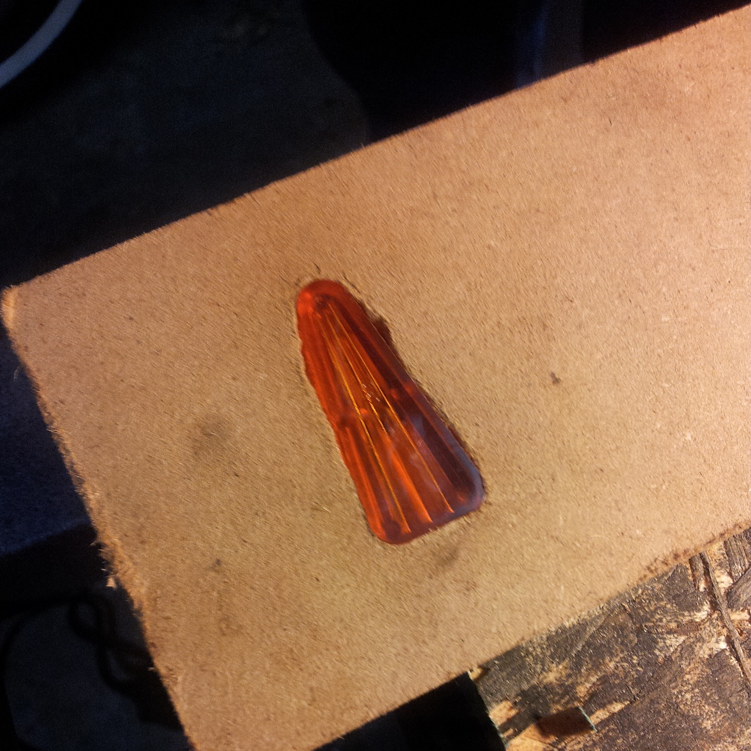
Here's a clear triangle insert
And here's an opaque one
The clear one lit up a bit more evenly, but it didn't really look that good, you could clearly see the hot spot where the led was located. Surprisingly I think the opaque one looked better overall, and other colors seemed less washed out, which is nice since that's probably my only option...
I then played around with led placement. Putting it more towards the center or ends didn't help much; the ends were still pretty dim. What did help was cutting a bigger hole. here's a single led, positioned similarly to the previous photo, but with almost all of the insert cut through the playfield instead of just one hole the size of the led
Probably good enough for me. I'll need to come up with a better way to cut those inner holes out, maybe another 3d printed router guide or something.
I also played with two leds under the same insert
This looks a bit better than just one, but not as good as I was expecting. The hot spots seem more pronounced. I'm not sure if I'll be able to position the strip to hold two leds inside the arrow or not (the clamps haven't arrived yet). This is where a lot of people seem to use multi-led boards, which might be worth it at least for the main shots? I'll have to look around
Cross posted from the original Pinside thread, this is one of many posts regarding my third homebrew pinball machine, creatively nicknamed 'P3'
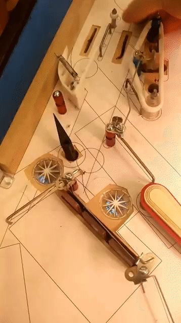
Since I had the playfield torn down, I figured I might as well install the inserts too. I've got a big bag of random inserts I've collected over the years from different stores, so I started laying them out. To keep things simple, I used one size of arrow (1.5" triangle) and three circles. I think the circles can probably be done with a forstner bit, but the arrow will need to be done with a router. Taking some advice from Johnsonvillebrat, I designed a guide for my router
and a guide for the shape
It took about 10 tries to get the guide just right for a snug fit (a big pain, since each print took 3 hours!) but I eventually got it just right
and made my first cut in the playfield
....aaaand immediately ran into an issue.
Can you spot the difference between these two arrows?
One is wider at the tip! I sorted through my inserts and found out that half of them won't fit the guide I made, which also means I don't have enough of the correct inserts for the playfield. I was planning on making them all clear, uncolored, for RGB lights, but I don't have enough of those. So I went to order more.
...aaaaand no one stocks them! (unless I want to pay $5 each shipped from europe) What? A transparent arrow should be like, one of the most common ones needed. Pinball Life (who has a great selection of inserts for homebrew) has six colors... but no clear. And they don't have any plans for restocking. The best I can find is that PBR has some opaque white inserts available, but I'm not sure how that'll look since every modern game I know of with RGB lighting uses transparent.
Luckily, I had one of those in my assortment, so I figured I'd stick it over an led and see how it compared.
...which made me realize I have no RGB leds. In fact, I have no real plan at all for how to light all these inserts! Back when I was first planning out this electronics system years ago when RGB was still a bit new, I figured I'd just get some 4-legged RGB LEDs, and then just stick them in a matrix. Except I don't have any boards designed to drive a matrix. And after wiring up the switch matrix, I really don't want to wire up another whole matrix with double the wires. It seems like today everyone is using NeoPixels and other individually addressable, chainable LEDs (well, besides stern, but), so I started looking into what'd be the cheapest, easiest, least messy way to get some of those installed. Luckily when I designed my MPU I added a spare connector for the 3 extra unused GPIO the RPi had, and I made sure that one of those was the DMA pin that's commonly used to drive these LEDs from a Pi, so I think I can drive them. If not I can get a FadeCandy or something. It seems like a lot of people are just buying FAST's individual LED boards, but they're $1.50 each, and need wiring to connect them all. So I ordered 5 meters of addressable LED strip (150 LEDs) off eBay for $15, and some mounting clips for $5. I'm hoping I can just string this through the playfield to reach all my lights, and use the spare LEDs in between as free wiring (just don't turn them on). Maybe that'll work, or not. I can always find a use for 5M of LEDs at worst though.
In the mean time I've also ordered a bunch of opaque white inserts from PBR, since they're cheap and I needed some other parts anyway. Hopefully they light up well. Maybe the opaque inserts will give it a more retro feel? Of course, I don't know if the random opaque triangle insert I had lying around is from PBR or not, so cutting (and thus, reassembling) the playfield needs to go on hold for now until the order arrives so I know whether I need to design a new router guide
Cross posted from the original Pinside thread, this is one of many posts regarding my third homebrew pinball machine, creatively nicknamed 'P3'
Ran a test cut of one 4x5" area
It turned out fine, no obvious issues.
so I went and did the whole thing. I took one of my rough manual cuts, and stuck it down with a bunch of double sided tape. In retrospect I should have used thinner tape, as during the cut I could see the plastic flexing downward before the bit broke through, but it doesn't seem to have caused any issues with the cut.
My first time running a real job on the CNC, probably took about 40 minutes. Plastic seems to have come out fine, and it at least fits on the playfield. Most of the holes are off center, but not outside the margin of error (I made every hole bigger than needed). There's a few places that need some correction, so I need to figure out how to do that. Aligning the plastic perfectly was a big pain, I don't think I could reliably get it matched up again. But I want to avoid doing stuff 'by hand' for risk of cracking the plastic. Maybe I'll need to use the router manually? Or try to run the CNC with manual control. Before I bother with any of that though, I should probably secure this down again and do some more heat tests.
I went in multiple times to try to do the corrections to the layout, but something just wasn't making sense. The corrections weren't all in the same direction, but different parts of the playfield tended to all need correcting in the same direction, and half the time that direction was opposite of how i'd already corrected those points before. In addition, the way I lined up the plastic so that it lined up with holes the closest resulted in it not being parallel with the edges, which didn't make sense either. When I lined it up with the edges of the playfield, right to the corners (where I know it should all match up), none of the holes lined up at all. So I stopped working on that until I could figure out what was going on. I measured various parts of the plastic and the wood playfield, and checked them against my CAD drawings, and they were all accurate. Then I got a t-square out to check if maybe my playfield somehow wasn't square. Nope, playfield was square. But the plastic wasn't! It had a 3/8" skew to it along its entire length. There must have been something wrong with the setup of the CNC causing it to list to the right as it moved up the playfield, so I'll need to figure that out. Never noticed in my test cuts since all of them were smaller. So that plastic is a loss for any real work. But knowing that it's wrong, I don't have to worry about fixing it the right way. So I just got out a router and adjusted all the holes by hand to line up enough. I'll reassemble the playfield on this bad plastic for now to test out the material.
Cross posted from the original Pinside thread, this is one of many posts regarding my third homebrew pinball machine, creatively nicknamed 'P3'
But before I can cut some new stuff, I need some drawings to cut! I took my scan of the original playfield, and converted it back into a cad drawing (what a pain!). Then I got that printed out on paper at 1 scale again, tore down the playfield, and laid the paper down on the playfield to verify everything, since I wasn't sure if the scans would be "square".
Sadly you can't see through paper (it would have been amazing to get this printed on something clear but as always I'm being cheap), so I had to use a small screw to search out all the holes in the playfield again for comparison
Some parts were spot on
Some were off, but very consistently so
And some things were so far off I don't know what could have happened...
Overall, the stitching seems to have worked pretty well, but not good enough to really be a go-to thing. In the future I'll need to be more vigilant about cutting stuff exactly matching the cad, and adjusting the cad as I go when anything diverges to prevent this.
I spend most of my day off today going through every hole again and manually adjusting my cad drawing (which the paper was printed from) to account for the discrepancies, so hopefully I'm now good to go. I'd like to avoid having to get another throwaway paper printed to verify all my changes, and I've got 3 sheets of acrylic ready to go, so I'm tempted to do a few test cuts on leftover stuff, then just get cutting and see how I do. Probably not the smartest thing to do but at some point you've gotta stop preparing and just jump in, and the cost of failure is theoretically pretty low (or it would be if I could find any reliable source of plastic locally, grr)
Cross posted from the original Pinside thread, this is one of many posts regarding my third homebrew pinball machine, creatively nicknamed 'P3'
Two months of no real progress on the game, but: I've got a CNC router!
It's... currently sitting on top of the bed in my spare bedroom, because I horribly underestimated how big it would be. But that's fine, not many guests during COVID. I haven't done any really big serious work with it yet, but it seems to work fine for my small tests I've run so far, so I don't think anything should change much.
I did some test cuts using a straight edged router bit (not sure the correct term for this), which was recommended for cutting plastics (since it doesn't have a helix to pull up the material). With a spare bit of lexan, it didn't do too well, sorta ripping up the edges and melting them a bit, similar to the issues I had cutting my lexan by hand with a drill. I got a sheet of 1/16" acrylic and tried that, and it cut much better. Not perfect, but definitely presentable. The only issue is that acrylic has a tendency to crack and shatter randomly. The router bit hasn't caused any of that yet, but when doing a whole playfield it could potentially cause an issue. I also tried another scrap of plastic I had on hand (which I think is PET-G, but I didn't label it), and it cut super nice. I'm trying to source some PET-G sheets locally to test out but I haven't found anything so far, so I'm gonna go ahead and try the thicker acrylic first. Acrylic also is (supposedly) what 70s+80s games with plastic playfields used, and what other homebrews have, so I'm still hopeful it'll work.
Cross posted from the original Pinside thread, this is one of many posts regarding my third homebrew pinball machine, creatively nicknamed 'P3'
After a few multi-hour sessions with the glass on, the plastic has finally started buckling. Worse, after I left it to cool off for a day, it's still not lying completely flat again. I assume if I stripped and repopulated the whole playfield I could fix it, temporarily, but not a permanent solution...
I've been told that this method worked successfully on some homebrew pins, but using 1/16" perspex (acrylic). When I went to my local plastics shop to buy some, they recommended I use lexan instead for this application, as it shouldn't react to heat any more than acrylic and would hold up to the pinball better, but months later when I finally unboxed the sheet and measured it, it seems to be 1/32" per my calipers. So maybe a thicker sheet would work, or maybe the material is wrong. Or maybe I'm missing something else... I don't really want to hand cut another one of these after all the effort the first one took either. Maybe I'll shell out to get one laser cut, if I can get a good cad file together...
I've also ordered a CNC router (https://www.v1engineering.com/lowrider-cnc/) that hopefully I can eventually use to cut new playfields and maybe plastic sheets (or even longer term goals, I get my own laser cutting head to attach to it), so maybe I'll wait on addressing this issue for a while. Moving back to a clearcoated playfield is always an option, it'll just add a ton more complications and steps to deal with...
Cross posted from the original Pinside thread, this is one of many posts regarding my third homebrew pinball machine, creatively nicknamed 'P3'
Got the playfield reassembled and have been playing a bunch of test games. No buckling on the main playfield at all. I've got a slight bubble above the upper left flipper, I think I just tightened stuff down wrong though, doesn't seem to be changing. Have to be very careful no screws are rubbing against the edges of their holes, and to attach stuff in a 'wave', to make sure the plastic lies down flat. There's a slight drop in the plastic over the screen from the weight of the ball but not enough to affect its travel or anything.
Plays much faster with the plastic compared to the paper (who would have guessed?). I'm not getting occasional airballs off the center bank, which isn't great, and some balls are flying right over the eject hole. I'll have to make some air ball guards, and might also turn down the flipper strength some, since it's a bit too much in some places. If you hit the left target on the center bank from the right flipper it rockets down the left outlane too fast to see.
While reassembling I also noticed that some of the post screws are starting to strip. Some of these should definitely be machine screws, but that can wait.. for now I'm just upgrading to longer screws, since the ones I had were only going 1/4" into the wood.
The upper magnet continues to cause me issues. Despite doing multiple tests showing that it could grab a ball from ~2.5" away with no wood in the way, it still can't pull a ball reliably off the post for some reason... It might work better if I had the post above the magnet instead of below, so it'd have more time as the ball drops, but it's probably still be sketchy. Again I wonder if having a large metal core covering this whole area would work better, or if having the magnet under just 1/32" of plastic is equivilant....
If I position the magnet at the far right, it can grab the ball 75% of the time, but it drops it too far to the right and it doesn't feed the flipper well. If I position it more to the left it feeds cleanly, but can't grab the ball. there's about 1/8" sweet spot where it mostly works, but anything can throw it off, definitely not reliable enough.
Additionally, I'm also having issues where sometimes the ball comes around the orbit so fast that it actually bends the post and gets wedged in between the post and the wood on the right, sometimes also lifting off the playfield somewhat. If I can't get the post more rigid, I'll have to abandon it since it's getting the ball suck...
Cross posted from the original Pinside thread, this is one of many posts regarding my third homebrew pinball machine, creatively nicknamed 'P3'
Installed the upper magnet. Needed to cut a 3" hole to fit it, but luckily that just barely left holes for the surrounding stuff that was mounted there. Right below the nearby target you can see one hole where one end of the ball guide goes, which I'm half certain is going to rip apart at some point since there's so little wood left there. Tried to design the mount to hold the magnet slightly below the surface so it won't scratch the plastic, but not sure how that'll work when the magnet is active... maybe I should cut a circle of plastic to 'float' in between them or something? I feel like overall I don't want it to be too much lower, or it may stretch the plastic or something
Cross posted from the original Pinside thread, this is one of many posts regarding my third homebrew pinball machine, creatively nicknamed 'P3'
After a lot of careful measuring, it's time.
The fit I'm going for is very tight. I'm about 2mm from one of the drop target mounting points, and I'm going to need to relocate one of the slingshot switches slightly, move a fuse block, and make a custom mount for the magna-save, but, it should work.
Printed this magnet bracket, and cut a small stick of 3/4" iron for the core (I think this is the right metal...)
20 agonizing minutes later, I have a hole
It fits! Barely. You can see the penciled outline of the drop bank on the bottom right, and the currently floating fuse block on the bottom left. I had some room to the top (left side of the playfield) I could have moved it to if necessary, but I wanted to keep it centered between the slings/flippers if possible
I then mount the control board very professionally, and hook it up. Success!
Lets get a game running...
The viewing angles aren't the best but I think it should be okay. Will have to wait until I get it in the game for that though. The supports are a bit too thick and stick out of the playfield, so I'll need to space those or something. Not sure how I messed that up, thought I specifically made them slightly short :/
Cross posted from the original Pinside thread, this is one of many posts regarding my third homebrew pinball machine, creatively nicknamed 'P3'
Reassembled and dropped it in the cab again for more testing.
Everything seemed to work fine. No mechs were sticking, no raising of the plastic anywhere. I left it sitting for a while with the transformer+electronics on in case that would trap any heat underneath, but nothing happened. I'm still quite suspicious, but I can't really think of any more testing I can do at this point, and the playfield does look so nice and shiny....
So I took the playfield back out, and disassembled the whole thing again. I'm getting very fast at this, but it's still a pain. One thing I'd try differently next time is the side rails. Currently they're under the plastic, but I think it'd be fine to have the plastic 1mm away from them. This'd save at least a quarter of all the screws I need to remove when taking the plastic off, and prevent the playfield from having time to sag while the rails are removed. Within a few hours of removing them there's a noticeable 1/4" dip in the middle of the playfield, which is more than I'd have expected, especially with all the drop target banks already removed... I assume my playfield wood just isn't as sturdy as what manufacturers use, but nothing I can do about that
With the plastic removed and everything stripped off, I have some updates to do that I've been putting off:
- the right controlled gate for the top lanes needs to be moved about 1/2" to the left to prevent ball hangups
- the right-most upper lane needs a new rollover drilled in line with the others, since previously it only had a 'bottom' row switch
- need to add lane guides to the upper lanes so the ball doesn't fall the wrong way
- the target under the upper left flipper needs some tweaking. The hole isn't big enough to fit it through right now, so I need to extend it, and I want to reposition the guide wire below it to give a better feed
- I've removed the upper left target (it was sort of under the ramp above the upper left flipper) since it can't be hit due to the pop bumper being replaced with a rubber (it wasn't really hittable before either), so now I can make a new guide going from the upper eject hole to the upper left flipper that doesn't have a gap in it for the target, which will hopefully improve that feed.
- widen a few holes and slots slightly since some mechs would occasionally bind a bit on the edges
Once that's out of the way, I'll move on to the fun part: cutting a 10" hole in the middle of the playfield for the LCD screen. No chances to mess up horribly here, nope...
And then I can cut another 2.5" hole for the upper magnet and finally get that installed again!
Cross posted from the original Pinside thread, this is one of many posts regarding my third homebrew pinball machine, creatively nicknamed 'P3'
No noticeable change in the plastic after sitting all day with the lights on it, so time to dig in. I started by just making all the holes for posts, guides, etc.
I've gotten pretty good at making clean holes, at least for smaller sizes, but for some reason they never seem to center well. Some I went to a bigger size, others I manually elongated by running the drill against one edge.
Luckily, with a new blade, making the slots and other straight lines isn't too big an issue. I score each side 3-5 times, then use a hammer to punch it out, and I get pretty clean lines (as long as I get the corners right)
Bigger holes cause issues. Once you get to about half an inch (or even 3/8 sometimes) the bits start to chew up the plastic. Depending on how bad it is I can sometimes clean it up with a blade but it's never perfect. I wish I had a better way to do these, but no method I tried (drill, forstner bit, spade bit, etc) was perfect. It'll be fine for a whitewood, but I think I'll definitely need to get a better one of these machine cut at some point if it all works out.
I'm finally at a point where I have most stuff cut out, enough to reassemble and playtest the game to see how everything works. I've skipped some of the guides, the drop target banks (since they're removed right now anyway), etc.
Cross posted from the original Pinside thread, this is one of many posts regarding my third homebrew pinball machine, creatively nicknamed 'P3'
Using my flatbed scanner, I scanned the whole playfield in, since this is probably my only chance to access it completely flat
I'm hoping that I can stitch these together and use them to update my CAD drawing to match the hand-changes I made when assembling, though I've heard mixed results about how accurate this can be...
Then I put down my sheet of plastic, which I think is 1/32 lexan, and started marking holes for posts.
The main worry with this plastic is whether it'll bubble and expand, separating from the wood, which I've seen happen when trying to make playfield protectors. This is a bit thicker though, and lexan, not PET-G; I'm hoping one of those two factors will fix that issue. To test it, the best thing I could come up with is just to heat it up for a long period of time, so I set it up with a bunch of incandescent lamps pointing right at it, for lack of any better options
I'll leave this on all day, and see if the plastic rises up anywhere. If not, I'll proceed with cutting the rest of the holes+slots, and reassemble the game for further testing. Not sure if I'll also cut the hole for the screen at this point, or play it some with the protector first before going 'all in' and cutting a 10" hole in the playfield.
Cross posted from the original Pinside thread, this is one of many posts regarding my third homebrew pinball machine, creatively nicknamed 'P3'
Game is getting increasingly hard to play due to the lack of a screen, so I decided it was time to bite the bullet and try installing the plastic sheet, which means I need to strip the whole playfield. Took it out of the cab for the first time in a while
In some places, I'm glad that past-me thought ahead and installed connectors
In other places, like the wires going to the trough mechs, I wasn't that smart, so I ended up cutting the wires, and I'll install a connector later. A few mechs I left hanging, since I didn't think to put connectors on them, and now they're wired in such a way that I can't easily add them.
Tear down went pretty quick and painless. There's not that much on top of the playfield, and all the drops have connectors so they're quick to remove.
The biggest pain was all the standups. They didn't get connectors either since they're so scattered, and some of them barely fit through the playfield. In a few cases I actually assembled them through the playfield to begin with, so I needed to disassemble the target again to get it out.
The paper has held up pretty well to being played on over and over.
When I first installed it I worried that the ball would rip it up when I started flipping but there's no tears at all, even in high traffic places.
I moved all the playfield components to a spare sheet of cardboard to keep track of them:
I wasn't very consistent about screws, posts, etc when assembling, and in some cases I even had to do stuff like grinding down plastic posts to make them shorter, so you really can't mix and match anything, and keeping it all straight like this is really important.
Taking off the paper reveals about what I'd expected: a ton of trapped sawdust everywhere. It's been messing with the ball and getting it stuck in places it seemingly shouldn't
It also reveals something I hadn't anticipated; the wood around every screw is slightly ripped up and standing above the playfield
I'm not sure if this is just normal, or if it's caused by me screwing everything in without drilling pilot holes. Luckily these sanded down easily without affecting the finish of the wood at all
With the playfield all torn down, next I'll need to start cutting the plastic
Cross posted from the original Pinside thread, this is one of many posts regarding my third homebrew pinball machine, creatively nicknamed 'P3'
Installed a tilt bob, which had to go on the right side due to how I'd routed the wiring, etc. Even in this position I'm still going to need to trim the rod some to keep it from catching on stuff. Plus I need to earplug it!
With that installed, I realized I still had no way to kill power to the flippers, so I installed some relays too. Now the tilt works properly in game, and the flippers also aren't energized when there isn't an active game.
While opening the game to check on something, I noticed I had four pinballs piled in the front left corner of my cabinet. Occasionally, balls hit by the right outlane saver will airball over the lower left flipper/guide and fall down in there, and rather than grasping around for them I just grab another ball
So I set up an airball catcher, made from scrap lexan and attached to the existing ball guide
In order to get the height right, I also had to put the glass back in, which was a problem since I didn't have any siderails. I dug a pair of stern side rails (from replacing with lollipop rails) out of my spare parts, and they seem to fit the williams cabinet fine. Eventually I'd like to get proper williams rails on there, but I need to get the secondary holes for the extra flipper buttons, so that's been on the backburner. Since the stern rails are narrower, they fit above the buttons fine.
My lockdown bar is also still covered in rust, so I grabbed one from my whirlwind for now, and for the first time actually had the game assembled with glass+lockdown bar. It's surprising how much of a difference this makes. The game feels much more like a 'real' game. A lot of the noise gets quieted down, which also makes the gameplay feel smoother. A big improvement, although I still need to get a coin door skin somewhere...
With the mechanisms quieted by the glass however, it becomes much more obvious that I don't have any sound effects! I think this is going to be a big focus soon; I need to start finding (or recording) sound effects and callouts for everything. I'm not really sure how I want it to sound either. Most card themed pinball machines are EMs, and the solid state ones fall into that weird early 80s state where the only sound effects that could be generated were laser blasts and explosions (Eight Ball Deluxe always stood out to me for this). By the time sound designers were free to use any sound effects they wanted, poker themes weren't really popular. I think the only two games that'd fit that category are High Roller Casino and World Poker Tour. For better or worse, the sounds on those have never really stood out to me, to the point where I can't actually remember what they sound like to use as a reference. For a while I was tempted to stick a chime box in this game and call it done, but I'd like to try to get some actual sound effects in.
For now, I think I'm going to try to make all the sound effects be related to actual poker. Chips clinking, cards being shuffled, etc. Not a ton to work with but maybe it'll be enough. Not sure how that'll feel as a pinball game either though....
Cross posted from the original Pinside thread, this is one of many posts regarding my third homebrew pinball machine, creatively nicknamed 'P3'
After more playtesting, I decided that it was too hard to catch the ball. With a game where not hitting the wrong things can be as important as hitting the right things, players need to be able to get some control. Even I was having trouble with this, and would often have the ball roll off the end of the flipper while trying to catch it, which I think is partly due to how steep my flippers are (at rest), and thus how shallow they are when raised.
When I originally designed the game I tried to copy the layout of my Alien Star, but I messed up somehow, and part of that was that I put in my flippers too steep. A while ago I picked up a spare gottlieb inlane guide, so I stuck this in my printer and took a scan:
measuring that picture, I got an angle of 119 degrees (probably 120 in reality since that's a nice number...), while my layout was 126 degrees (fun fact, williams inlane guides are 125, so I somehow mistakenly made williams inlanes...). So I made a new inlane guide with a 120 degree angle:https://cad.onshape.com/documents/cf8933508c54fdc1d2e1cbec/w/8de46f8a59b2e2a9657a1015/e/ce2603cfd473c1490421177c
Installing it on the playfield made it look way more dramatic than it was, with the giant gap between it and the slingshot:
But the actual difference in the flippers was pretty reasonable:
So I went ahead and adjusted the left side as well, and moved the slingshot down to compensate
You can see from the old lines and holes how much stuff moved... I'm ending up with a lot of holes in my playfield! When I try to make the plastic for this, I'm going to have to be careful to note which holes are 'current' so I don't use the wrong ones when reassembling.
Cross posted from the original Pinside thread, this is one of many posts regarding my third homebrew pinball machine, creatively nicknamed 'P3'
For the second aspect, I wanted to see whether the shot behind the pop bumper could be made if you removed the pop bumper. So I took out the pop bumper:
Gobble hole? No, I need to fill it. What do I fill it with? Well, lets just cut another hole with the hole saw and save the piece
Not a perfect fit, but for testing it works better than expected.
Now... Can you shoot into that area to the right of the back lane?
No problem!
Originally I was going to consider redesigning the lanes area to add another 'shot' here if this angle worked, but I realize there's already a handy blue target right there, that can no longer be hit by the pop bumper, so I don't really need to design any new shots. Just add an arrow insert pointing at that target and make it a jackpot or something, and it goes from 'least useful target in the game' to 'major shot'. Considering the amount of work necessary to redo this area to use two shots instead, I'm inclined to just go with the four lanes from the previous approach and this 'shot' here.
Now for the last bit, should I put something where the pop bumper was? I did a bunch of test runs, dropping the ball from each of the upper lanes, rolling it down the metal guide, shooting it from the upper right flipper, to see exactly where the ball traveled, what angle it was going at, etc, and then took a deep breath and installed two posts.
This is another case where I hate trying to place stuff, since getting these two posts positioned at the proper location and angle to get the bounce I want could take a lot of trial and error, leaving my playfield filled with holes, but I don't really have any better ideas on how to approach it. Originally I'd hoped that both ends of the rubber would be located on my disk I installed, so I could just replace it if necessary, but it was clear from my drop tests that at least one end would need to be on the playfield.
Now... does it work?
Success! I'd like it to feed a bit higher on the flipper, but proof of concept is working good. I think eventually it'll need be lowered a bit (but not so low that it obstructs the right flipper's path to the upper scoop. A bit of nudge when the ball lands on the rubber should help too. Before fine tuning further I'm going to play the game more and see how this affects other parts of the game, but throwing it around by hand it seems to be working generally how I'd like:
I had also planned to maybe put a standup behind this rubber to be hit by the right flipper, and it looks like from a very early shot you can hit the bottom edge of the rubber, so that does look possible, but I'll wait to do that until I'm sure I like this rubber and its placement. I might also experiment with alternate coil stops/etc on the right flipper to make it shoot at a higher angle.
Cross posted from the original Pinside thread, this is one of many posts regarding my third homebrew pinball machine, creatively nicknamed 'P3'
Added a post on the upper right of the lanes, and luckily it doesn't seem to affect orbit shots, so I think that converting my two rows into one 4 lane row is doable. Plus, since I still have the switch down below, I don't need to make any further playfield changes for now to work with it. The action is also not too bad. The ball doesn't stay up there long, so you have to lane change fast, but it's not impossible. I feel like the lane change on some games makes it almost too easy.
I do wish the gates were a bit more bouncy though. You only get maybe one bounce off each of them even on a strong shot; I'd like it if the ball bounced back and forth a few times. Not sure if that's something you can do much about though. Maybe I'll play some some foam or springs eventually.
As you can see in the image though, there's one small issue: the right gate is a bit too far to the right, so the ball gets hung up from time to time. I'll need to move it a bit to the left eventually, but for now it doesn't get stuck too often.
Cross posted from the original Pinside thread, this is one of many posts regarding my third homebrew pinball machine, creatively nicknamed 'P3'
Did some testing with the plastic covering... I previously tried to do a full playfield protector on one of my games, but as expected, it warped and raised off the playfield, presumably due to heat expanding/shrinking. However there are many european pins that have plastic playfields and don't have that issue. I'm not sure if that's due to the material (IPDB claims they're plexiglass but I don't know how they tell) or the thickness (I've now gotten confirmation that at least one manufacturer, Interflip, uses 1/4" plastic over their 1/2" plywood).
I cut two strips of plastic, one from the new sheet of lexan I bought for this project and one from the scraps that (I think) are from the previous full protector I made (hard to tell these sheets apart :/ ), and attached them to a piece of plywood, then I stuck it in my Dracula (the only game I have handy that's all incandescent) to 'bake'. After 12 hours, I could see some slight raising on the old material, and minimal/none on the lexan, which is promising at least... I'm not sure exactly what conditions are needed to reproduce the issue though. Is it just heat expanding the plastic? is it air under the plastic heating due to inserts? Presumably it's more noticeable on larger areas with no anchoring, but that's harder to test.
I also did some more practice cutting of my spare sheet of lexan. Trying regular drill bits and forstner bits. The forstner bits seem to leave more of an edge on the holes. Both seem to have some risk of creating weird spirals of plastic (like on the rightmost hole in the picture). Cutting on wood seems to help, I think since the bit can't 'punch through'. I was able to get pretty clean holes with a drill bit at medium speed. Too fast or too slow tended to cause issues. I also need to make sure to hold down the plastic around the bit as much as possible, to keep it from pulling the plastic up.
Experimented with cutting straight lines as well, and found that it's possible to do pretty cleanly with an exacto and ~5-10 passes. Definitely preferable to power tools. Can also be cut with scissors but they're hard to get into the holes since you're not cutting from the edge.
On last annoying thing: apparently the plastic sheet I purchased is 1/32". It's been a while, but I thought I'd requested 1/16 as 3/32 wasn't available, and I felt like that was the most that could be potentially layered on top of a 1/2" playfield without affecting the mechs+etc sticking through. I'll still use the sheet though since I've already got it, and hopefully it works okay. If I run into issues with it flexing or expanding, but everything else is fine, then i'll consider buying another thicker sheet
Cross posted from the original Pinside thread, this is one of many posts regarding my third homebrew pinball machine, creatively nicknamed 'P3'
With the gate figured out, I'm almost ready to tear the playfield down and start cutting my lexan covering. There's ones area I'm still not satisfied with though: the upper right area
my original design for this was intended for it to be two offset rows of three lanes, using the shot behind the upper drops as the third upper lane. Like on EMs, you'd shoot up there, bounce around, and try to nudge into the lane you want, then fall down into the pops. But it isn't working out the way I wanted.
1. due to the path of the ball coming through the spinner, I had to remove the mini post I was going to have on the far right of the lower lane, so now balls tend to just roll off to the right instead of going over the rollover
2. there's only one pop bumper, and it's not directly below the lanes. you don't get balls going back up through the lanes much. instead, the ball rolls down to the pop, and gets shot back up to the area below the lanes, and then just falls back down to the pop again. Sometimes this can repeat 5x before the ball works its way around the pop and back into play. Not satisfying.
3. Due to the small size of the divider posts, it's much harder to nudge the ball where you want it than it would be on an older game, which would use 1/2" posts.
4. again, due to the way the ball comes in from the spinner, there's a gap between the rightmost post and the one way gate. When you shoot through the spinner, about 40% of the time, the ball bounces off the left gate and falls perfectly back through this gap, never entering any lane.
5. the lanes are so close to the top of the playfield that there isn't much room for the ball to move around. This also means that the exit of the lane behind the drops doesn't flow well since it just bangs into the top arch. I originally wanted it to shoot around the orbit.
6. because this playfield is longer than an EM, being in a whirlwind cab, the lanes are even farther away from the player, which makes it harder to figure out where the ball is going or nudge appropriately
Part of the small spacing is caused by the lane behind the drops, but I don't want to lose that shot since I want to use it for jackpots during multiball. At a minimum, I need to adjust the playfield somehow so that the ball can't escape the lanes on the right, but I'm considering reevaluating this area further...
A simplification of the lanes?
Basically changing my two sets of three lanes into one set of four. This would solve the gap on the right issue. It should function ok, as long as the rightmost post/divider doesn't interfere with the spinner shot. There'd be no room or time for nudging, so this would have to be just a lane change affair. I'm not sure how much the ball would bounce around up there though, with the upper rail so close to the posts. Would you even have time to read the ball movement and try to change lanes before the ball had fallen into one?
The pop bumper will still feel a bit weird with the ball popping into that dead area repeatedly though. I'd like to move the pop bumper down some, but moving the entire bumper isn't something you can really do once you've cut its hole, so that'd have to wait for another whitewood...
Maybe get rid of the pop bumper completely?
Although I like having a pop bumper (especially one pop bumper, which recalls games like Stars, Meteor, or TNA), I'm not sure it fits this design that well. it tends to make play on the upper playfield very chaotic. If you don't hit the drop you're going for on your first try, you're out of luck because the pop bumper will pop the ball around and take out 2-3 drops before you can get control again, which is half your hand. I'd hoped it be more of a 'danger' off in the corner, but during play the ball tends to hit it any time it's up there.
One thing I originally envisioned for this layout was that the center drops would be angled the other way, allowing you to bump the ball back towards the upper left flipper off them, but the spacing for that didn't work out. Adding a small rubber here might make the play up there more interesting, allowing you to bounce the ball back to the upper flipper. I could put a target on the back of that rubber too, to give the upper right flipper another target to shoot for. It was supposed to be able to hit the target on the upper left, under the ramp, but it turns out the flipper can't hit something that high up, so that target is basically useless.
Instead of lanes, I could try to do something like many williams EMs have?
A kickout hole with rubbers on either side to alternate the award. It's a fun area to play in, trying to nudge the ball back and forth to get it to land on the award you want. I'm not sure there's enough room for it, or what the awards could be though.
Or maybe something completely different. Get rid of the upper section completely. No more one way gates; the ball always does a complete orbit. Lots of other ways you could take this, but here's one idea I came up with:
The shot next to the drops is still there, it's just redirected to feed the right orbit cleaner. Hopefully with this the ball could feed down the right to the inlane, or get caught be the magnet to feed the upper right flipper. The area below it could be an extra hard skillshot: plunge just to the beginning of the arch to arc the ball into that lane.
Or maybe that lane is also shootable via upper left flipper? The pop bumper would need to be removed to unblock the shot, but...
Now you have two shots from the upper flipper. One feeds the left inlane to the lower left flipper, one feeds the right lane to the upper or lower right flipper, or shooter lane. I've always thought that was a cool idea, although it makes more sense on a more combo/flow game. Demolition man technically pulls it off, but the side ramp is so hard to shoot compared to the subway that everyone just goes for the subway. With equally easy/hard shots the flipper could act as a 'skill diverter' letting you intelligently set up more combos. Maybe that could still make sense for this game though, as long as the rules set up something for each lower flipper
These last two redesigns look a bit weird on first sketch, but there's a lot of room up there to tweak things and make them shoot smoothly. Having a large empty area like that feels weird to me though... As a designer I like to use up every single square inch of playfield, so having a large empty plastic like that seems like a waste, but maybe it's for the best?
Tomorrow I'm going to pull out the pop bumper and patch in some wood in the hole, and see how the upper area plays like that. Does it shoot better? Can an extra rubber there make the ball bounce back the way I'm thinking? Can the upper left flipper hit that rightmost shot? Can the upper right flipper hit that rubber?
I'll also try placing some more posts in the upper right area, see how far to the upper right I can put stuff without interfering with the spinner shot. I imagine if you get too close to the upper arch the ball is going to hit the post, since it's probably rattling around a bit as it meets the rail...
Cross posted from the original Pinside thread, this is one of many posts regarding my third homebrew pinball machine, creatively nicknamed 'P3'
I tried to write some code to make use of the left orbit (under the ramp), and realized I had no good way of detecting shots through there. I had originally placed a rollover under the ramp, and a hanging gate across the exit from the back the ramp. That way, shots that hit the rollover first would count as orbit shots, and if a shot just triggered the gate, I'd know that was the end of a counter-clockwise shot from the spinner as it entered the left lane. The rollover under the ramp also doubles as a way to detect balls that, coming around from the spinner, fall under the ramp instead of going down the left lane, so I can raise the ramp temporarily to let the ball out. Which is good since that happens *a lot*. That should have all been good, but it seems it's possible to shoot under the ramp and not trigger the rollover, probably due to the width of the ramp and the ball bouncing around. So often I was just getting the gate switch, and had no way to tell which direction the ball was going, which was a problem. I also wanted to improve this area to give a cleaner feed to the left lane from the spinner, and prevent balls going under the ramp from the back so often.
Enter: the longest gate ever
Now it senses balls coming through the left orbit, using the same hanging wire as the previous gate did, and prevents balls from going under the ramp from the back, instead feeding them to the left lane. These little gottlieb L brackets for mounting gates+spinners are a life saver, they allow me to do all kinds of weird things with gates. Just need to make sure they're aligned properly
Cross posted from the original Pinside thread, this is one of many posts regarding my third homebrew pinball machine, creatively nicknamed 'P3'
I realized that the top lanes still did nothing outside of the skillshot, so I decided to add a quick rule that one lane would give you more magna-pulses, but this reminded me that I still didn't have any ability to sense the flippers being pressed. I've been making do so far with using the secondary buttons for stuff like navigating menus, but you can't really use those during gameplay, and I want to add a status report soon since I'm getting to the point where the screen is getting filled up with information.
Since I'm using directly controlled flippers with high voltage contacts, this isn't as simple as it would be with software controlled flippers. I don't want to use switches on the flipper mechs like early games did since that seems to have some lag sometimes, and I can't add switches to the buttons since they're already double stacked for staging, so I'll need to do it electronically. Looking at other games, system 11, WPC, and gottlieb system 3 use opto-isolators to sense the HV signal going to the flipper, but I didn't have any on hand and have never used those before, so I tried to come up with a simpler solution.
My thought was, since my flippers are grounded by the cab switches, I should be able to just hook some 3V circuitry in parallel, since ground is the same for both. I put a diode between the chip and the cab switch to prevent the high voltage from going backward, and used a 74367 tristate buffer chip, so I could hook the switch matrix column to the enable to simulate a physical switch. A quick test with a breadboard hooked up to the switch seemed to work, so I assembled this one off board
Optimally this would have been part of my MPU board, but I wasn't sure what the circuit would look like at the time, so I left it off. Once it's battle tested I'll probably design a new MPU with the added stuff but for now this'll have to do.
Wired it up and ran into an issue... hitting either flipper button registered both sides. of course, not something I ran into when testing just one side with the breadboard. The signal seems to be traveling backwards into the playfield, through one coil to the HV line, then back through the other coil. I ended up just putting some beefy diodes in line between the flipper coils and the contacts to prevent that.
Also had an issue where the right flipper button (row 1, column 8 ) was also registering as the switch in row 1, column 1. Left button (row 7) was fine. Eventually concluded this was just due to the order I scan the matrix (row 1->8 for each column 1->8 ). I must be scanning it faster than the circuit through the chip can react, so it's still reading as closed for the next column (1 is after 8 ), but corrects itself before it gets to the other rows. Added a tiny delay after finishing the last column to account for that.
Cross posted from the original Pinside thread, this is one of many posts regarding my third homebrew pinball machine, creatively nicknamed 'P3'
Another lingering problem I've been having is with the slingshots and pop bumper. Originally I was going to control them through the driver boards like everything else, but I realized I'd be able to use 2 boards instead of 3 if I powered them separately. So I figured I'd just drive them with Gottlieb pop bumper driver boards. I had some spares, and they're purpose built for this purpose. But for some reason I can't seem to get them to work well. Unless I gap the switches incredibly wide, the boards will rapid fire. So after a lot of fighting with that I decided that I could make a better pop bumper driver board!
Instead of relying on a 555 timer and some capacitors to handle timing and debounce, I'd use a cheap CPU (a PIC16F1827 8 bit CPU) and code it to work exactly how I needed. Plus, then I could use a single board to drive all three of my coils (these gottlieb boards are so spread out and wasteful!). Since I already had the wiring harness set up to use them, I designed the board so it could work with multiple original 6 pin connectors, or with just two custom connectors (one for inputs, one for coils). And since the CPU had 15 IO pins, I made it drive up to 7 coils (why not?). Still the same size as the original, and mounts using the same standoffs:
I built one up, populated the components for three coils, and hooked it into the machine. It took some tweaking, but the results are quite good. I'm now able to gap the switches incredibly close, so the kickers are super sensitive, and I can adjust the pulse time to get the strength where I want it. The pop bumper is now much stronger, and the slings got set a bit weaker since they've always been concerningly strong when they did get triggered
Curious to see how it performs compared to an actual gottlieb, so at some point I'll build another of these and stick it in my Alien Star, assuming I can get all the connectors to reach
It mounts in a standard slingshot bracket; when the coil energizes and pulls the plunger (which attaches to the bottom of this part) down, it also spins around about 120 degrees in its channel.
The thing fits in about the same area as just the coil (and could be made smaller too, but I sized it around the hex base which is 9/16 for easy mounting with a wrench), so there's no clearance issues compared to the plain post that was there before.
I had to rearrange things slightly since the existing post+hole wasn't in the proper position for a gate (which would optimally be right above the wire guide, but in the end it works since it also gives me more room to bounce the ball around a bit, giving the player more reaction time, which was another goal I had when reworking this area.
Will have to give it some more playtesting to make sure it holds up well... In the long term I'd redesign this area a bit further around this new mechanism. The two rollovers aren't needed anymore, since it's basically impossible for the ball to go the wrong way which also means two switches saved (I think my matrix is nearly full), two less cuts needed to be made in the playfield (and the eventual plastic cover). The post can be moved a tiny bit closer to the drops below. I can use a shorter metal rail since I don't need to have it extend up to work with the up-post, or maybe a small custom-cut guide can be made to fit below the post and provide a smoother transition to the outlane. Instead of the temporary red post I added on the left, I can shape the inlane guide above it to fill in that area.
It took about 12 prints over 10 hours to get everything right since I didn't really plan this out before hand, and didn't know what measurements I was working with, but in the end it's working smoother than I expected, so not bad for a day's work
Cross posted from the original Pinside thread, this is one of many posts regarding my third homebrew pinball machine, creatively nicknamed 'P3'
Lots of playtesting happening while I try to figure out what direction to take the code in. I've gotten a few others besides myself to playtest, such as my old college roommate who dropped by for dinner one day:
He's not a pinball player, and has probably played 20 games of pinball in his whole life, so it was interesting comparing how he played it with how other, regular pinball players did. Another interesting difference though, is that he knows how to play poker, vs another playtester who plays pinball a lot, but doesn't know poker too well. One person trying to actually play poker hands, go for good hands, etc even though their accuracy and control were minimal while another mostly ignored the hands. I need to make sure that the game is fun for both types of players.
Watching people play has also given me more chance to actually watch how the game physically plays and I've noticed some areas I don't like:
The right inlane/outlane area was giving way too many inlanes vs outlanes. The metal wall on the side of the slingshot to smooth the orbit feed doesn't help either, as it's effectively making the inlane even wider. I thought from my initial design that it'd be very outlane heavy but either the wood outlane wall is bouncier than I expected, or the angle the ball tends to come in just is leading to that sort of path... I added a mini post with a small rubber right above the inlane guide, which seems to help a bit:
My ability to place the post is a bit limited since I need to make sure not to interfere with the orbit feed from the diverter, so I couldn't really place it much higher, or any more to the left (which I wanted to do to make the outlane 'wider')
The left outlane had similar issues. The ball was going down the inlane much too often, and again I couldn't really change the size of the inlane that much since it's also the left orbit return feed. So I needed to play with the outlane instead. I started by swapping the left slingshot post from a star post to a thinner post, but that didn't have much effect. So I started moving the post down+right, keeping the front 'face' of the slingshot the same since I still need to keep it aligned with the switches. It's now down as far as it can go without touching the upper switch, which also required dropping from a 2.5" rubber to a 2" rubber. Still, the ball tended not to go down the outlane that much. I also added an old data east half post rubber to it, since I've found these tend to have a deadening affect on the posts, but it didn't really have a noticeable affect.
I also noticed that the magna save wasn't getting used. At all. Whenever the ball came over to this area, it'd either be down the outlane or inlane instantly; there was no time for nudging or reacting, let alone using the magnet. Eventually I'll probably move the magnet lower, since the slingshot has gotten so much shorter, though I don't think that will help the speed issue that much. I'm not sure if the issue is just that the game is too fast, or if the geometry is also having an effect. I added a mini post in this outlane too, again being careful to not affect the orbit feed while moving it as far to the left as possible, and also added a post above the magnet. I'm hoping that this will cause the ball to bounce off the posts more, leaving it in range for the magnet to be used. This whole area is a bit cramped... I wish I had had a widebody cabinet to use instead of a standard width, mainly for this left side. The feed down the left wall could really use another inch or so to play with, but oh well.
Playing with posts like this is a bit nerve-wracking. I can picture there being a lot of minor adjustments I'd like to do, but once you put a post in one place, you can't put another too close or the holes will interfere with each other. Right now I'm 'testing' by holding the post upside down so the rubber is at the proper height while trying to roll the ball through in all kinds of directions to see how it plays, which is working okay, but you can't really do any advanced testing. Most commercial games have slots for the posts to be moved through, but that is still only one axis, and those slots are difficulty to cut by hand. I'm almost tempted to make a custom little assembly with large washers above and below the playfield, so you can then just drill like a 3/8" hole in the playfield and position your post anywhere in there...
The lower/mini playfield entrance is also giving me issues. The ball tends to rattle a lot more than I expected coming down the outlane, so sometimes the ball is going the wrong way when the post is down. Sometimes the down post and its hole cause the ball to do weird things too, since the post hole is in the path of the ball (which I've learned from owning a Jurassic Park is something to avoid at all costs...).
I'd REALLY like to have a little diverter gate here instead of a post, but the area I have to work with is extremely limited. I picked up a Stargate recently, and saw that they had a really cool diverter mech in their outlane. It's a rotating gate, but it operates via an up-down post mech, with a spiral path around the plunger, so the gate/plunger is forced to rotate as it moves up and down. I bet that mech would work perfectly, if I could somehow find one to use, but I've only ever seen it in Stargate. Maybe I can fabricate one with my 3D printer...
I'm also going to play with the post to the upper right, try to move it down and to the left as far as possible in order to guide the ball more towards the mini playfield entrance. I can't move it too far though without blocking the outlane drain path, and I need the one way gate on the inlane to still work, so this may end up being a custom shaped 3D printed post?
The star rollover on the left got positioned too far to the left, so it's possible for the ball to roll down the guide smoothly and not trigger it. I can't really move the rollover though without cutting a new playfield or something. Multiple playtesters commented that the ball feeds to the lower flipper very fast; you need a very quick reaction to flip in time once you realize the ball is going to the mini playfield instead of draining. So I may try to reshape the guide here in to try and slow the ball down and force it to go over the rollover as well.
One last area of minor concern:
Occasionally a fast right outlane drain will self-lazarus off the mini playfield exit gate. It's not too often, so I'm not that concerned, but I'd rather it didn't happen. Usually games have 'biff bars' (or whatever the official term is) to prevent this, but since I actually want balls to be savable from the mini playfield flipper, I can't have one here. Don't really have any ideas on how to prevent this
Cross posted from the original Pinside thread, this is one of many posts regarding my third homebrew pinball machine, creatively nicknamed 'P3'
More code progress, working on the first mode...
As I've actually been able to play, I'm realizing just how hard it is to get a straight/flush. The odds in real poker at random are about 3-4%. Not exactly how frequent you'd want a multiball to be... I had figured it'd be much easier here, since you're able to choose your hand, but it turns out that aiming is hard. Playing test games, I was managing to get a straight maybe 1/8 times. Not horrible, but still not too good. I also realize a general flaw with awarding modes+multiballs off your hand is that if you get 4/5 cards for a straight, that doesn't carry over. Most games if you drained while trying to get multiball, you'd at least have saved progress, but this is all or nothing. Also, getting a pair is super easy, probably too easy.
So I'm playing around with various ways to change this up. First, I'm thinking of other ways to get the various multiballs, such as using your poker winnings to 'buy' them. That way as long as you win your hand, you're still making progress towards features, and if you can pull off a good hand, you get rewarded with an instant multiball. Still some stuff to work out here though. I don't want to end up with big menus for purchasing things or anything, I'd like most of the choices to be made during gameplay.
Alternately, maybe I keep a separate progress tracker for each mode. Getting a 3 card straight would give you some progress, a 4 card would give you more, etc. Or I can combine this with the 'purchasing' mechanic, lowering the price of the multiball based on previous progress.
Another option would be to have some other multiball awarded for more standard things. I could place some shots around to spell 'LOCK' and light locks for a separate multiball, to at least balance out the game more from relying on the hard to access hand multiballs. I'm there's many ways to set this up, but I'm hesitant to add something which could pull the focus away from playing the poker hands.
I'm also playtesting the ability to undo cards. Right now I have the magna save and outlane vuk tied into the same 4-light meter, so I also added the ability to undo your last dealt card at a cost of two magna-save pulses. currently this is triggered by the start button, but eventually I figure it'd either end up as the action button (if I can manage to mod one into this williams cab), or as a cheat button below the shooter (callback to Jackbot).
Lots of options to play with, but they all require playtesting. Which is good to be doing anyway, although the game is still a bit barren right now. It's also giving me more data for stuff like the outlanes. I've moved posts around, added rubbers, etc, to try to make the outlanes fairly drainy (since there are options to save the ball), but still savable with some nudging.
What I'm finding interesting is how little chance I get to nudge things. The ball moves around so fast that it's either in the inlane or outlane often before I can react. I'm not sure if the game is just playing faster than other games (it doesn't feel that way too much), or if something is making the rebounds less predictable, etc. I'm wondering if some of this may be the paper covering the playfield. Could it play different enough from wood to cause issues? I also know that the plunge and upper lanes have some issues due to bits of wood stuck under the paper, so maybe there's more of that that I'm not aware of. Hopefully that should be handled once I get the inserts/plastic figured out. I need to spend some more time doing some practice cutting before trying to hand cut the full sheet I've got. I've also been looking into CNC/laser cutting options, but haven't had much luck so far. When starting this project I'd hoped to use the local makerspace since they have a CNC router and a laser cutter, but they've been closed due to covid Considering purchasing a cheap 2x2ft unit for myself, but I'm not too knowledgeable about the options on this front.
Cross posted from the original Pinside thread, this is one of many posts regarding my third homebrew pinball machine, creatively nicknamed 'P3'
I'm hoping to use a plastic sheet on the playfield instead of having to manually cut all the inserts and deal with clearcoating, etc, but I wasn't sure how I was going to handle the star rollovers. The sheet will end up pretty similar to a Hardtop, and I know that star rollovers cause tons of issues with those, with each hole needing to be manually cut out for alignment, rollovers raised, etc. Plus I'm hoping to cut this plastic by hand, and drilling holes in it isn't the easiest, especially for large holes. Doable, but I also have 11 rollovers on my playfield right now (and could really use a few more), so it's something i really don't want to mess with. I looked into using eddy sensors but I can't find any good cheap source for them.
I thought back to earlier EMs, especially some ballys, which have tons of small, ~1/4" rollover buttons, and I figure that those would probably have a much easier time dealing with a hardtop. But with how my playfield is designed, buttons that small will run the risk of not being triggered by the ball. Plus I don't think those small bally rollovers are available anymore.
So i'm trying my hand at 3D printing some custom rollovers:
These are designed to have a button slightly smaller than my 3/8 bit, to give a small bit of wiggle room when drilling the holes, but hopefully not enough to get the ball hung up on. They also seem to be just big enough to still have similar sensitivity/range with a normal rollover star. The transition as the ball rolls over isn't quite as smooth (partly because it's not smooth like a star and partly because my 3D printing isn't that smooth) but it doesn't seem too bad.
They'll need some tweaking, but I think they should be usable.
Cross posted from the original Pinside thread, this is one of many posts regarding my third homebrew pinball machine, creatively nicknamed 'P3'
While doing some gameplay test I had my first 3D printing casualty... Luckily it wasn't from the ball hitting it, but from a design flaw. My shooter lane diverter gate is using a regular ball gate (what bally tended to use in its outlanes), and they aren't too accurate since they just use a relay to spin the gate. When the gate is resting against the side rail it's fine, but when it's energized and out in the playfield it can have a lot of variance. In this case it ended up stopping above the 5 bank of drop targets:
You can guess what happened next...
I've now added some software compensation to prevent this from happening:
You'll also notice my new gate is orange. I ran out of my original spool of white PLA plastic, so now I'm trying out some orange PETG; recommended to me by by another homebrewer as being much stronger than PLA and good for pinball mechs. It took me five prints to get a usable gate though, and it's still a bit messy, so I need to work more on dialing in the settings for printing with the different material.
Cross posted from the original Pinside thread, this is one of many posts regarding my third homebrew pinball machine, creatively nicknamed 'P3'
Still alive! Been distracted by other stuff but I've been slowly making code progress on the game.
I had started by trying to code the first multiball, but I was making lousy progress due to running into a lot of bugs and having issues debugging them. After a few days making no progress like that, I decided to put a halt on game coding, and focus on making the dev/testing/debugging workflow better.
Testing the game physically was a big pain. Originally I was trying to run the code from my desktop, but the game was at the other end of the house. Then I tried doing remote desktop from my laptop, but it still wasn't too good. So I started planning on how to rearrange my office to accommodate the machine, so I could have easy access to it while developing, but I couldn't really come up with any good layout. There's just no comfortable way to be sitting in an office chair near a desk but also be able to reach a whole playfield. Plus, I realized that my projector mount is too tall to fit in my office
So cleaned up my work area, cleared out my livingroom (which has a high ceiling), and set up a new testing/work area there, with all the best comforts available :
As cushy as this is, I still would prefer to do my coding from my office workstation as much as possible, so also worked improving my 'visualization'/'simulation' more. Even then though, I still found that every time I deployed new code to the machine I was running into tons of hard to reproduce bugs, so I spent some more time adding a ton of logging to the code, and improving how the logging works to make it as easy as possible to examine different subsystems, etc.
The real big change though came after that. I captured some weird bugs on the machine, and then took the logs back to my desktop to investigate, but it was slow going reading the logs and attempting to figure out what was important when trying to reproduce the issues virtually. In particular I had one log file that contained nothing but a log of every switch closure/opening that I was staring at since there were some weird switch issues (flickering, etc) going on.... and I thought to myself, with this info, couldn't I just play back the entire game?
So I spent a weekend writing a 'recording'/'playback' system that could read any log I give it and run the game on my PC to recreate the exact sequence of events. With that, I could add tons of breakpoints, pause and step through the code, etc, and pinpoint the issues. Plus, the recordings make perfect automated test cases, so I now have a growing collection of recordings of resolved issues that can be automatically run to verify the game is functioning properly when I change more stuff.
This had further benefits too beyond tracking down bugs too. When developing new bits of the code, I no longer need to click through the game to access the areas I want. I have premade scripts for "complete a hand", "qualify multiball", etc that I can just run whenever needed, which has made development much nicer.
Plus, since it's a recording, I can speed it up. Here's a video of the game playing back a recording of collecting 5 cards, starting multiball, and then lighting a jackpot:
Overall, I'm still spending a lot of time working out bugs, and figuring out how to handle various standard game things like various priorities overriding each other while I develop the game code, but it's been worth the time to slow down and improve my workflow. The game is going to require a lot of code, so if coding the game isn't fun by itself, then I'm in trouble!
Cross posted from the original Pinside thread, this is one of many posts regarding my third homebrew pinball machine, creatively nicknamed 'P3'
Not much progress lately, all my time has been taken up by other things
I installed an up-post next to the magnet to catch the ball as it comes around the left orbit
Was a bit nervous about the installation since this wasn't at all planned for, and I had to just eyeball the location, but luckily it did barely fit
The post itself is a bit smaller than the sleeve, but the sleeve itself is nearly touching the magnet, so I definitely can't really get much closer
Sadly, even with this set up, the magnet still couldn't grab the ball. In retrospect I should have just screwed a regular post in at this location and tested the magnet with that first. If I pushed the ball even 1/4" closer to the magnet, then the magnet had no trouble grabbing the ball, but with the ball leaning against the right wall, there was just slightly too much distance. I can't move the wall, since it's part of the shooter lane, and I can't move the magnet, since it has to be aligned to drop to the upper flipper.
Again, I wondered about having an exposed core, and whether that would be enough, but I didn't want to drill the playfield to find out. Before setting up some test cuts on my spare playfield, I decided to test out the best-case scenario: instead of an exposed core, just expose the whole magnet! I stuck the magnet under the lexan sheet on my test playfield, and ran some wires to test it:
No problem here. The magnet easily grabs the ball from at least 1-1.5" further than it does with 1/4" of plywood in the way. I'm now very curious how this compares with the large exposed cores Stern uses now, but still don't want to spend $50 to find out. Even that wouldn't be needed though, if I do end up going the route of just covering the entire playfield with a plastic sheet, which is looking more and more enticing as a solution to many of my issues.
The main problem right now is actually cutting the sheet. Circular holes shouldn't be a big issue, but I'm not sure how cleanly I can make the slots for the target banks. My biggest worry is all the star rollovers. I'd have to cut holes for each of them that align very well with the holes in the playfield, and then raise the rollovers up to be flush with the sheet. I'll need to practice some more with my spare material and see how cleanly and accurately I can make all these cuts. Long term I'd probably need to get this laser cut, but I haven't had any luck finding a place to get a cut this big made yet
Cross posted from the original Pinside thread, this is one of many posts regarding my third homebrew pinball machine, creatively nicknamed 'P3'
Last month I picked up a world cup soccer, and while shopping it I noticed that it had the same style one way gate as one of my spares, with a second wireform to hold the gate open, and that this was the type used by TNA, so it's available from PBL. I did a rough mockup of the part from measuring it on WCS, and it looked like it'd fit, so I ordered the mech from PBL for $30, rather than making another custom mech.
Of course, it didn't quite fit, but I was able to make due. I ended up having to move the mount for my support rails in a bit, and then mounted the gate mech on top of the rail at an angle. I could have put it in a nicer position, but I'd mounted the switches for the lanes in the way. As I probably could have predicted when I decided to do all my switch wiring with one mech still missing, it was a bad idea.
When I hooked it up to test it first, the gate didn't work. I could hear it buzzing, but it wasn't quite strong enough to pull the flap in. If I gave it a small nudge it'd work though. Once I turned the playfield over, gravity did the work for me and it worked fine. In retrospect I realized that this is another mech designed for 50V, not 25V, so I guess I should be happy it works at all. On the plus side that means that it's pulling such minuscule power at 25V that it'll probably never overheat, even without any PWM. I left it on for two minutes and couldn't even feel any warmth from the coil. I like the idea of being able to just have gates and diverters constantly energized, vs having them react when they know a ball is coming at them. There's a lot of times in other games where I get caught by surprise by the orbit coming around or not coming around, etc, since there's no indication on the playfield. At a minimum I think it'd be nice to have a little stop sign insert or something if you're going to do that...
Using a transformer that only outputs 25V seems to be my single biggest mistake so far with the whole project.... It's just continually messing me up since it's not something I ever really thought about before. As much as I like the gottlieb flippers and the general retro feel I think that, if I do another homebrew after this one, I'll either switch to all 50V, or at least get a transformer that can support both, and just use williams mechs...
Cross posted from the original Pinside thread, this is one of many posts regarding my third homebrew pinball machine, creatively nicknamed 'P3'
In order to prevent the arcing from destroying my relay contacts, I switched to driving the magnet using a TIP36C that in turn was grounded via the relay instead. That way, the high current is switched by the transistor, so there's no possibility of arcing, while the relay still allows me to control the 50V coil via my 25V driver FET. I mounted the TIP36 on a small bracket made from left over aluminum to act as a heat sink.
With this, the magnet functioned properly, no more locking on, but it also somehow managed to blow my 50V supply's fuse. Even upping it all the way to a 10A slow blow didn't help; I couldn't energize the magnet for more than 1 second. I think this must have something to do with the caps on my voltage doubler, as the lower rated fast blow fuse directly powering the magnet isn't blowing...
Regardless, none of this seems to matter since the magnet still can't grab the ball from the orbit very well. Even with, a medium speed ball thrown by hand, the magnet seems to have almost no effect, let alone being able to grab it. At this point, seeing how bad even 50V is suited for this task, I'm going to stop bothering with this approach for now, and just install a diverter of some kind, as I can't see any of my other ideas improving on it enough for this to be a reliable function in the game. I'm hoping to have at least one multiball be all upper flipper based, inspired by classic lawlor layouts, so having a reliable way to feed the side flipper is a must...
Cross posted from the original Pinside thread, this is one of many posts regarding my third homebrew pinball machine, creatively nicknamed 'P3'
3D printed some brackets for the screen. It's funny, prior to getting a 3D printer "how do I mount a screen under the playfield?" was a really big question mark on my project's todo list. With a 3D printer, I had it mounted just fine with 5 minutes of modeling.
Made a test screen hole in my testing playfield plywood. Messed up the cut spectacularly somehow, my whole rectangle was like 1/4" skewed. Not sure how I managed that when I made it by tracing the screen, but oh well.
I also tried mounting a test piece of 1/16" lexan over the hole, to see how much it deformed. I screwed it in at the same positions that the nearest posts are on the real playfield, to get an idea of how well it'd be held down. I had problems instantly with a bit of warping, since my holes weren't placed perfectly.
I think that to use this on a real playfield I'd need to pre-drill all the screw holes with a slightly larger bit, so it has some room to slide around while I'm tightening everything down. Then I'd have to work from the center outwards as I attached everything to try to keep it taut.
My initial test of 'pressing it down with a finger' didn't seem very promising. I could flex the hole down way more than I can on my Black Hole. I still don't understand how the super thin window on black hole is so sturdy when every plastic I've looked at is so much more flexible...
In the end though, I realized I shouldn't be testing with my finger, but with a ball. Setting a ball in the middle of the hole has almost no effect on it, and it seems to roll across it fine. At worse, I can always make a second layer of plastic just for the screen, to bridge that section if it becomes an issue, so this approach still seems viable.
Another benefit I thought of is that I could conceivably mount my magnets way closer to the ball. With wood on top of the magnet, it seems like most playfields are still retaining 1/2-3/4 of their thickness to keep the wood solid, which means the magnet is probably about 3/16" away from the ball in the best case. With a plastic covering, I should be able to cut that down, which should make the magnet stronger, and might help with my issues on the upper magnet. I'm not very familiar with the physics of magnets though... I'm curious how this would compare to the large metal cores on games like TWD. Is a 3/16 thick, 3" wide metal core on top of a magnet generating a larger field than the entire winding itself does?
Next I need to figure out if I can use my star rollovers with it. I used them a lot in the design since they're easy to cut the holes for (compared to a rollover switch slot), but I know I've heard about issues with them and playfield protectors...
Cross posted from the original Pinside thread, this is one of many posts regarding my third homebrew pinball machine, creatively nicknamed 'P3'
Received my replacement screen today:
Will try to hook it up this weekend and get it displaying some images, then do some text cuts on my spare plywood to figure out mounting, and see how well my lexan sheet will work.
In other fun, my flippers have suddenly gotten very weak (can barely make it up the ramp). I hadn't actually had the game on in the past week or two since I'd just been working on code, so I have no idea how long it's been like this. Always a fun issue even on regular machines, so I'm sure it'll be fantastic trying to track it down here...
I wish there was a reliable way to quantify flipper/coil strength so I could really check on stuff like this, make sure I'm not going crazy, etc...
Finally tracked down my weak flipper issue... I replaced the bridge, no change. Replaced the capacitor, no change. Checked signals with a scope, everything looked okay. Cap smoothed the signal out well, peaks were proper height, everything seemed proper. Then I realized... the fuse was blown. I never even considered checking that, since obviously the flippers were working. Something about the way I hooked up two bridges in parallel, one with a smoothing capacitor on it, must have allowed enough voltage to build up through just one side of the AC, through a common ground or something, that allowed it to still get the flippers enough power to flip. Not really sure how that could be, but. I thought I had replicated the circuit gottlieb used on black hole accurately, but the one difference was that I had a separate fuse for each bridge (although I only fused one side of the inputs) while Gottlieb had a shared fuse for both bridges.
I assumed that was just a cost saving measure, but maybe it's actually because of this?
I also realize now, looking at the schematics, that they don't actually fuse the DC side of the bridge, which is interesting. I guess they figure that the per-coil fuses will usually catch those issues? I guess they usually do, at least in my experience. I definitely didn't fuse my solenoids enough overall. I put separate fuses for each flipper and bumper, but the controlled coils only have the one shared fuse on their driver board. More concerningly, I've never blown the on-board fuses for some reason, but I have blown the rectifier fuse when a coil locked on, despite the rectifier fuse being 8A slow blow and the on-board being a 4A fast blow. Hopefully that doesn't become an issue.
I've also designed another iteration of my driver board since my rev 7 that I assembled still had mistakes, though I haven't ordered it yet since I'd like to get some more boards done for a combined shipment. This time, I restarted from scratch. My previous schematic had been carried over and repeatedly modified since my original rev 1 board back when I started learning how to design boards, and was a bit of a mess.
Before:
After:
I'd also been repeatedly running into issues when designing the boards trying to fit them in a 2x4" footprint. Over time I went from 13 FETs to 16, added driver chips, fuses, test points, indicator LEDs, etc while still using the same size board, and it had gotten really hard to layout. This time I scrapped the voltage indicator LEDs, and dropped from two fuses (one for each bank of 8 drivers) to one fuse. Originally, I had designed the board so each bank could be operated completely separately, and could be configured with pullups for PNP transistors or pulldowns for NPN transistors, so that it could also be used to drive an 8x8 lamp matrix, but that use has sorta disappeared in the intervening years.
Those part removals combined with some tricky layouts let me finally get all the transistors layed out neatly. This also means that I can now stick both solenoid connectors on one side, and keep all the low voltage signals on the other side of the board, to clean up the wiring a bit more
Rev 7:
Rev 8:
Yesterday my second screen shipped out, so of course today my original screen I ordered from China arrived out of the blue.. Only took 2 and a half months. This one included a USB power cable, which is nice since now I won't accidentally fry anything by using -12V, but it's also weird, since USB is 5V. As far as I can tell, the boards are identical. Not sure if there's something I can't see that's different or if one of the sellers was wrong about the supply. Was also able to confirm that my first screen is still good, so I must have only damaged the driver board, so now I've got a backup. And soon I'll have two boards and 3 screens. My attempt to get a cheaper screen from china has now cost me about $130 I guess that's what I get from ordering something from overseas during a pandemic though
Cross posted from the original Pinside thread, this is one of many posts regarding my third homebrew pinball machine, creatively nicknamed 'P3'
My screen still hasn't arrived, so I gave up and ordered another one. Hopefully it will arrive eventually..
In the mean time, I tried out an idea I'd been toying with for a while. I don't know where any of my lights will go, or how the art will look, and it's hard to play with that, so why not make some temporary artwork?
I dug out an old projector, and hung it from a 2x4 sticking out from my upstairs landing, and lined up the game underneath, then I loaded up a quick mockup:
I expected it to be a bit hard to play like this but it was actually surprisingly easy to ignore and play like normal. The quality isn't very good though; the cards aren't readable even at 1080p. With a 4k projector this might be workable beyond rough prototyping, but it'll probably work for now. I also had to put the projector really high up, probably 10+ft off the ground. Gets to be a real pain turning it off and on without a remote
With this I'm hoping I can get the game much more fleshed out before needing to commit to making a new playfield and moving everything over
Cross posted from the original Pinside thread, this is one of many posts regarding my third homebrew pinball machine, creatively nicknamed 'P3'
Coded the logic for actually determining which hand won, and displaying the best 'hand' from each hand of 7 cards. The code for finding pairs, straights, etc was surprisingly simple and fun to write.
Since it can identify what hands you got, I can now tie that into what modes/multiballs are enabled at that point. Unsure what I should do if you manage to get multiple different hands.
For instance, what if you manage to get three pairs? Technically only your better two pairs will count as far as the poker game goes, but if each pair qualifies a mode, should you have the choice of which one(s) to play? Should only the higher two pairs' modes be lit, effectively making lower cards' modes harder to get?
If you get a straight and a pair, and then you play the mode you get from the pair, does the multiball you got from the straight go away, or could you go play it after finishing the mode?
If you qualify a mode, but then immediately go into the shooter lane to start another round of poker, should you lose that mode, or should it still be available? Should you be able to start a mode mid-way through a hand?
So many questions... Luckily the decisions on these aren't really hard to change the code for, they could even be settings technically, although I'm not going to bother coding any settings menu or anything since I can just edit the code I'll probably go with the most restrictive options for now (if you take a mode you lose your multiball, etc) just so I don't have to deal with coding a mode select screen yet.
Cross posted from the original Pinside thread, this is one of many posts regarding my third homebrew pinball machine, creatively nicknamed 'P3'
Coded some initial spinner rules. First time you shoot the spinner, it stops it in the upper lanes. Next time it orbits around back to the left flipper for a 2x spinner shot, and stops it in the lanes. Then you get two orbits before it stops it, etc.
Coding this was way harder than that sounds, due to me not really thinking about 'shots' and such when I designed the playfield. A ball shot through the spinner could go in one of six lanes. Or it could fall back through the spinner. Or fall down the shooter lane. Or it could manage, theoretically, to go below the left one way gate and continue on to the left. When the gate is open, it will usually go all the way around, triggering the left orbit switch and the left inlane on its way down. But it could also fall short into the upper eject, or go under the ramp, or fall even shorter into any of the lanes, etc from before.
Originally I figured I didn't need to care about this too much. I'd just consider a shot to the spinner as whenever the spinner suddenly spun a few times. But when I'm purposely designing the code to let you repeatedly rip the spinner, it's very likely the spinner will still be spinning somewhat by the time you rip it again, or you could even go right under it while it's spinning, so I ended up with a ton of code for different edge cases trying to detect when the player does a successful orbit or not, multiple timers going on, etc. It's a bit of a mess, and it's going to be even more of a pain to debug if something goes wrong.
It would have been really nice to close up some of the areas a bit more so I could know 'for sure' whether a ball passed through there, rather than having a big open area up there for the ball to bounce around in. Too bad big areas for the ball to bounce around in are fun...
Scoring wise, I'm trying to sorta take a page from Meteor, since I like the way its spinner value is continually fluctuating. For the first iteration of that, my attempt is to make the spinner score more when you having matching numbers of drop targets down on each bank. For instance, the spinner starts at 10 points. You knock down one target on bank A, that goes up a bit. You knock down one target on bank B as well, that number goes up even more. Two targets down on each bank is better than one, etc. I'll try to balance it so you can get the spinner up really high, but at the same time if you hit one stray target it may ruin it completely.
Hopefully this will also encourage people to 'shoot around' more, instead of finding one or two banks they feel safer on and just picking targets off those
Cross posted from the original Pinside thread, this is one of many posts regarding my third homebrew pinball machine, creatively nicknamed 'P3'
Coded the basic structure of the skillshot. I'm pretty dissatisfied with most skillshots in games currently. Most seem to either be 'just plunge the lit lane', or plunge to a flipper and hit a lit shot. You don't really care about your plunge at all. Some games like Deadpool make it a bit more interesting by locking in your lane choice. Most games that actually require you to plunge to a specific spot (such as Taxi) just make you learn one or two plunger positions, which I think can get boring once you've learned them, since at that point you're just slowing down your game to squint at the plunger. My goal here is to have a lot of different places to plunge to, and have the context of the game make you change which one you're plunging to frequently.
There are seven different places to plunge to:
Red: plunge just far enough to clear the diverter. Diverter will close, leading ball to right inlane
Orange: plunge so that the ball hits the lower magnet switch, without hitting upper magnet switch. Magnet activates, pulling ball to the left and feeding upper right flipper (well, hopefully, if I ever get it working)
Yellow: if you plunge past the magnet and hit the upper magnet switch, you'll fall back down and feed the right inlane, similar to the red skillshot
Green: The lower 3 lanes. Not sure what will happen with each lane yet, maybe one will be lit as an extra target
Blue: Upper 3 lanes, same as green
Pink: plunge and fall into the upper eject which will then feed the upper left flipper. Really hard to do, worth the most
Purple: Hard plunge all the way around and feed the left inlane
The Pink and Purple skillshots are made harder since there's a one way gate to the left of the lanes, blocking them. Currently I have it timed so it's open for 2 seconds, then closed for 2, so you'll get redirected to the lanes or let through based on your timing.
Your current 'bet' amount is determined by where you plunge, so you can choose to bet a little or a lot while still keeping it 'pinball'. I'm thinking the bet amounts will be percentages of your total 'bank', so you'll be forced to bet more later in the game. You can return to the shooter lane at any point while playing your poker hand by shooting under the upper right flipper, so you can adjust your bet if your hand is looking better or worse.
In addition, there will be an award on each skillshot, that you can only get if you 'call' your shot by selecting that award with the flipper buttons. Currently it's just points, but I want to eventually put other stuff in there to mix stuff up. If it's only ever points, they'll either just be ignored, or they'll be so big they're unbalanced, so I like to put 'in game' effects into stuff wherever possible. But that will have to wait until I have more game coded to affect.
The graphics themselves on the screen are pretty basic right now, but serviceable. I kinda dread getting to the point where I actually need to make this stuff look nice somehow. Even for a simple screen like this, I think more code is dedicated to drawing and updating the screen than there is to the actual skillshot logic... It must have been nice in the DMD or alphanumeric games where you could often just slap some text up and be done with it
Cross posted from the original Pinside thread, this is one of many posts regarding my third homebrew pinball machine, creatively nicknamed 'P3'
I've spent a good amount of time playing with the upper magnet. It's positioned next to the shooter lane, right orbit, so that it can drop the ball to the upper right flipper.
The magnet had two use cases:
1. for the skillshot, if you plunge the ball up so that it stops next to the magnet, and then the magnet activates, pulling the ball sideways from the shooter lane to then release it to the flipper
2. to feed the upper flipper via left orbit shots. this is the main use case, with the skillshot just being a bonus. I didn't really forsee a problem with this while designing, but I've come to realize that this just isn't how magnets are normally used in machines. Games like Twilight Zone will stop a fast moving ball on an orbit, but they have the magnet directly under the ball's path. The magnet acts only as a ball grabber, not a diverter. Most cases I can find of magnets being used as diverters are things like TWD's crossbow, or WCS's lock. WCS is the closest to my use case, since it specifically grabs a moving ball, stops it, then drops it. But even WCS has issues grabbing a fast moving ball.
I quickly discovered that my original plan of wiring and mounting this magnet the same way the magna save is mounted just won't work. The magna save coil is being powered using 25V, while most newer games use 50V for their magnet. So I hooked up my 50V line to my magnet relay, instead of 25V, and... immediately fried my relay. The 50V is strong enough that, when the relay deactivates and its contacts move apart, the voltage will just arc across the gap and continue powering the magnet while melting the contacts. I had a similar issue with the 5-bank reset coil, and was able to fix it by adding a 10uF, 300V capacitor across the contacts. For some reason this doesn't work on the magnet. I wondered if the magnet was stronger, but the magnet actually has more resistance than the drop target coil. My random relay was only rated for 3A@25V though, so I ordered a really beefy relay, which was rated for 30A (!). I think my magnet should be drawing about 10-12A at 50V, so that should be plenty. But that relay also had constant arcing issues. I tried bigger snubber capacitors, other snubbing solutions, even disassembling the relay and physically bending it so the contacts are farther apart, and nothing helped.
It seems like switching 50V@10A just isn't reliable via a relay somehow, though I don't understand why. Modern games all control their magnets via transistors and mosfets, although I don't know if that is specifically to avoid this issue, or for other reasons. The problem is, I can't use those here, since my 50V has a separate ground from my 25V. My next plan is to get a TIP36C (which is what williams used for their 50V coils in the 90s), and then try to use a relay to switch the gate (instead of having a microcontroller switch it like normal) which feels like horrible overkill, but it may work. Even at that point, I'll still have issues because I can't PWM a relay, so I'll basically be running the magnet at full power. I'm not sure how long I can power the magnet like that, hopefully it's long enough to get the ball settled.
The magna save is also a completely 'below playfield' magnet, with no visible core. Adding a core that goes all the way through the playfield helps make the magnet stronger, and I assume that this is why games like TWD, which need to grab a ball shot at their wide bash toys, use an even bigger exposed magnet core. At first I figured I should just order one of those larger exposed cores, but they're incredibly expensive somehow (the large core costs more than the magnet itself!). Even a regular size core is expensive. I don't really want to spend that much money on something that may not even be useful, so for now I've just bought some 3/4" steel roundstock that I'll use to test the smaller exposed core. I can't find any info on how much stronger this make the magnet.
All this is still up in the air, too, as I don't know if the magnet will be able to grab the ball properly even with a large core and 50V, given the crazy speed my left orbit shot has. I've spent a lot of time trying just to get the 50V to work, and still haven't been able to even do a single test yet to see if the 50V can grab the ball since it keeps melting stuff
I'm also trying to consider other approaches, such as replacing the magnet with a physical diverter, but currently I can't find any good way to fit one in with my current constraints, and I would still need a magnet or an up post to hold the ball for a reliable side flipper shot after the diverter gets the ball to the flipper...
I may also try putting an up post in the shooter lane, specifically to stop the ball as it comes down the lane from the left orbit, and then using the magnet to pull the stopped ball over the flipper. I am running low on drivers for the coils though, so I want to avoid adding in more coils if possible...
Cross posted from the original Pinside thread, this is one of many posts regarding my third homebrew pinball machine, creatively nicknamed 'P3'
Got the basic habitrail installed. Made a half height, low quality mount to hold the other end, which seems to work okay.
It looks like I can make the curve on the entry mount wider for a smoother feed. This is the original:
And here's my current iteration:
Mounting the entry mount was also an issue, since I didn't really plan for that. I ended up putting it on a standoff on top of one of the existing ramp's mounting holes, but I still only have one screw holding it. It seems to work okay, so I'll leave it for now. I could probably extend another support out to the posts behind the 2-bank if necessary, but I don't want to cover the playfield any more than necessary.
I also needed a place to mount the switch, so I stuck a microswitch through a small gap. To prevent airballs, I put holes on the top to screw a sheet of clear plastic into. Still need to figure out how to attach the plastic on the left side of the ramp. I don't understand how Mars never has airball issues on its ramp... seems hard to believe that they managed to make it the exact height needed for their flipper strength, especially since I'm using the same flippers!
This is my final entry design. Looks pretty weird, but it works. :
I had to add some side rails to keep the ball from falling off, especially at higher speeds. Lock post worked on my first try with a random guess for the pulse length, which surprised me.
While it's nice to know this works, I probably will avoid locking multiple balls this way, since I don't have any way to mount a switch behind it to know if it failed to release a ball due to the ramp positioning. Sadly, this was the only position I could fit the post mech in, so I'm a bit constrained here. I'mthinking I'm going to have most multiballs work by locking one ball on the ramp, and then you get a second ball to plunge, and the ramp ball is released once you hit a switch. Maybe there will also be something to let you short plunge and combo up the ramp to lock a second ball, for three ball, or a rule about locking both balls during MB to release a third. Since there's no auto plunger I can't really have a normal add a ball. I feel like multiballs lately have been a bit boring design wise, so I'm hoping to do more stuff with multiple phases like DE used to do, or maybe more advanced stuff like a special multiball that you can only work towards qualifying while you're already in another multiball, at the cost of ignoring the current multiball's jackpots to make that progress...
For normal ramp shots, I programmed the game to engage the post as soon as the ball makes the ramp, and then disengage once the inlane switch registers, but I had issues with the ball bouncing over the switch since it was just dropping off the end.Inspired by Metroid which I saw at Pintastic last year, I made this end cap for the rail to make the ball drop nicely.
It worked, but I didn't like how it looked, so I made this instead, which seems to work fine and looks more natural:
Cross posted from the original Pinside thread, this is one of many posts regarding my third homebrew pinball machine, creatively nicknamed 'P3'
Here's a big case of 'wish I was using MPF'... Testing live on the machine was a pain since it was at the other end of the house from my regular computer. So I wanted to be able to easily test stuff virtually. MPF has a nice application for this. Lets you import a picture of your playfield, then drag and drop switches, lights onto it. Pretty handy, so I recreated it using my new rendering capabilities. Not a ton of work in the end, although mine lacks some polish...
Squares are switches. Red means closed, yellow/white means open. Left click to toggle open/shut, right click to quickly press the switch and release it again. Diamonds are coils, they turn red when energized. The white circle above the right inlane is a light, currently off, currently wired up as a 'lower ramp w/lit'.
Another in the left outlane will turn green when the mini-playfield is enabled, triggering the down post to let the ball in. Hopefully I can use this to get a slightly better feel for where lights will go.
I also added some code to do stuff like automatically opening the drop target switches when the bank resets, auto closing the shooter lane switch after a ball is released from the trough, etc. Stuff that would happen physically on a real machine. Otherwise it gets to be a pain to use, since the drop target coils would repeatedly fire until you remembered to click each switch again
Cross posted from the original Pinside thread, this is one of many posts regarding my third homebrew pinball machine, creatively nicknamed 'P3'
Code can't get very far without some read-outs. I don't have any lights yet, so for now my 'screen' will have to do. Currently that 'screen' is a 50' HDMI cable running to my livingroom TV, but it'll do.... I spent a long time trying to find a good R-Pi compatible graphics library that would work with Typescript/Node. For some reason, everything seems to have been abandoned 2-3 years ago, and doesn't work with modern Pi operating systems. I'd be fine with even coding the graphics from scratch with a plain OpenGL context, but even a simple library to provide that seemed to be missing.
Eventually, I found a simple library that supported things like basic shapes, images, and text, that was designed specifically for RPi game dev, but had been abandoned partway through development. The author's last update said that they were working on keyboard/mouse support, since without that a game graphics library isn't very useful. Well, it's useful to me! no keyboards here...
Only problem was, it didn't work with the latest RPi OS, since they introduced a new graphics card driver, and it wasn't compatible with Windows (my dev OS). So I dug in, forked it, and made my own version with RPi 3 support, some features and bug fixes, and, with one late night hacking session, a shaky but usable windows port. Not too bad, all things considered. The nice thing about this, vs using an established library (if one had existed), is that if I find any other bugs or shortcomings, I can just easily add whatever I need, since I'm already maintaining my own fork.
With that out of the way, I got some initial status displays set up. Very rough currently; I am not in any way an artist. Hopefully I can work up something half decent for the screen at least, but actually doing some art for the playfield is probably beyond me... More mountains to climb down the road
I can add more cards from the drop targets
No scoring or ball logic hooked up yet though... I also need to figure out what exactly is actually going to happen once you complete a hand. To keep with the 'real poker' goal, technically you should have a final opportunity to bet before your opponent reveals their cards, so I figure you'll need to shoot a shot that can hold the ball to finally flip the cards and declare a winner. In this case, my only ball holds are the upper eject hole, the ramp, and the shooter lane, so I'll have to figure out some logic for that, as well as how exactly you can 'fold' if your hand is looking bad. I'd like it to be something on the playfield, vs some menu interaction, but it has to be something very hard to hit accidentally....
Cross posted from the original Pinside thread, this is one of many posts regarding my third homebrew pinball machine, creatively nicknamed 'P3'
Began work on the habitrail for the ramp, to return the ball to the left inlane. I 3D printed some clips with flat bottoms to make it easy to hold the rails while I align them and work. The plan is eventually to either use some brass and solder it, or try to braze some steel, but for now, I'm using some easy to bend 1/8" copper wire (and cheap, since it's just on spools at Home Depot) to get it right and test things. I'm curious to see if the clips can hold up to soldering/welding, it'd be convenient.
The actual alignment is a bit iffy; since my ramp model didn't match the actual model that means the habitrail I drew won't line up with the physical ramp either. I tried to eye-ball adjust it to match where it looks like the ramp actually is, but we'll see how well that works.
The actual attachment to the ramp will also be weird. It was designed to connect to a plastic tube that goes across the playfield, and didn't have much flow. Originally I just sorta hand-waved this part as "I'll make something to hold the habitrail, can't be that bad", but now I'm at the part where I need to actually figure out how to connect a ramp whose shape I don't know to the habitrail I haven't built yet.... Here's my first attempt. I'll probably just have to print this a lot of times to get the fit right, assuming the basic shape even works.
Cross posted from the original Pinside thread, this is one of many posts regarding my third homebrew pinball machine, creatively nicknamed 'P3'
Earlier, I went searching for an LCD to put in the middle of the playfield. After a lot of digging, I ordered this 9" screen from AliExpress. Seems to have HDMI support and can be powered with my ATX power supply, but it's hard to tell for sure. There's a ton of different badly documented screens for sale, with conflicting information about what they support or how to drive them. It seems like there's really only two driver boards floating around, one with VGA support and one without, judging by the pictures, but some of the items for sale are clearly wrong about what they're offering. Lots of fun. But for ~$30, I'll take some gambles. Any screens for sale from more reputable US sources seem to be $100+ which is a bit ridiculous. Originally I planned to just buy a monitor and strip off the case, but it's hard to even find a 9" monitor, and the more common 10" won't fit my playfield.
Sadly it's been more than a month since I ordered the screen, and it still hasn't arrived. Tracking last showed it leaving China on 3/30, so not sure if it's gotten lost or just stuck in customs or something forever...
Not a super big deal, I guess, since I don't have any way to really mount it yet.
I'm investigating different options for plastic to cover the hole. Not sure what material is best as far as being pretty sturdy but also thin and scratch resistant. Based on the Voyager homebrew, I'm also wondering about just using a single large sheet of plastic for the playfield as opposed to recessing a smaller cover. I wouldn't have to worry about routing out the recess for the window, or about doing any inserts either, and no need to clearcoat. A lot of other possible issues arise though, so that'll need some more investigation. Once I can find better what material to use, I'll try to order some sheets for experimenting
Cross posted from the original Pinside thread, this is one of many posts regarding my third homebrew pinball machine, creatively nicknamed 'P3'
While getting some basic code running to reset the drop targets and eject the holes, I suddenly lost an entire bank of solenoids. Inspecting the board, I eventually figured out that the board had been repaired so many times as I modded it to test different things that one of the traces carrying the solenoid ground had just gotten ripped off completely. At this point it probably had 4 jumpers on it already, and multiple cut traces, plus some of the mosfets had been replaced three times, so I decided it was time to junk that pcb and build a new one.
One of the main issues that required all those modifications early on was my changing requirements for how the inputs would work. First I'd had them active high, then active low, and then I'd had to change which pin they were. Back when that happened, I redesigned the board to add some more configuration points, so each I/O could have a configurable pull up/down, as well as fix some other pain points. I added LED indicators that the fuses were good, test points for the voltages, and combined my 6/6/4 pin connectors into two 8 pin connectors. A big goal on these boards as I design them further is just making the connector count as small as possible, since they needed to get unplugged so often. I'd actually had the new PCBs on hand for months, but hadn't needed to actually use one yet, so I started assembling:
Sadly, I discovered an issue with my design early on: at some point I had mirrored some of the components. For the mosfets, that wasn't too bad; just turn them around, but I'd also mirrored one of my 16 pin chips, which resulted in the horrible hack of mounting the chip upside down:
Sigh. I guess another pass at the design will be needed down the line. It'll work for now though, just hard to mount
Cross posted from the original Pinside thread, this is one of many posts regarding my third homebrew pinball machine, creatively nicknamed 'P3'
Switch and coil wiring complete!
It's hard to really grasp it from the pictures, but for comparison, here's the relatively empty bottom right corner with a few switches wired from before:
And after:
This area can still use a bit of cleanup, but I ran out of my little metal strips for wiring support as well as the plastic ones.
Also visible here is my attempt to save some more solenoid drivers: two gottlieb pop bumper driver boards. These are wired up to the slingshots. It seems to work fine, and makes me curious why Gottlieb still used EM style driving for their slings while using driver boards for their pop bumpers. Eagle eyed readers will also note that one of those driver boards says NG on it. Surprise surprise, that board was... not good. Instantly locked on one of my slingshots. Genius. I also figured I could very simply enable/disable these by just hooking their logic ground to one of my driver mosfets, but it turns out that makes them glitch and fire randomly when you turn them on and off, so I reverted to doing what gottlieb did, and cutting the ground signal to the switches.
Some more wiring pics:
I was able to mostly follow my sketched wiring from earlier without issue. The one place where it got weird was the mini playfield at the bottom. Since there's no support rail out there, I ended up having to run the solenoid wiring along with the switch wiring around the right flipper to reach it. I'd planned on it going around the lower edge, or between the drops and the flipper mech to leave all the area between and above the flippers open for lights, but there just wasn't room
Out of 62 switches, I only had three wiring issues to fix on my first switch test pass, which is nice. Very glad I didn't mess up a whole column or anything. There doesn't seem to be any sure fire way to confirm that a matrix doesn't have any issues, but I knocked down lots of drops and hit lots of switches, and didn't get any incorrect readings.
With that out of the way, I was able to get to the most important part: getting something on the playfield to react!
Now I can start actually coding a few simple rules, and try to play some test games where I imagine different targets are lit and shoot at them to try to get an idea for how my rules to work, and I won't have to stop every 30 seconds to manually reset a bank of targets or eject the ball from a hole
Cross posted from the original Pinside thread, this is one of many posts regarding my third homebrew pinball machine, creatively nicknamed 'P3'
In the midst of wiring, I've been taking some breaks to start on the code. Against my better judgement, I'm going to attempt to write all the game code in Typescript (a type safe superset of javascript), and run it via Node off the Raspberry Pi. I'm a bit worried about performance, but I figure I can always optimize it, shirk off some duties (such as video or sound) to a C backend, or upgrade to a Pi 4 or a x86 based board with a Pi compatible GPIO header at worst. Why Typescript? Because I've been using it at work for so long that trying to use most other languages is unbearable. Typescript is just so nice and developer friendly...
Hopefully this all makes vague sense to people who haven't coded a pinball machine before:
I also am going to try to take a different route from how (to my knowledge) all other pinball games are coded. I've worked with/explored a lot of systems (early williams/bally/gottlieb, wpc, MPF, skeleton game, etc) and they're all very much focused around a central concept: events come in (from switches, timers, etc), and then the code listens to those events, and sets some state (light on/off), fires some coils, etc. It seems to often lead to bugs where lamps get stuck on, balls get stuck in holes, etc, because there's state where there shouldn't be, or there isn't state where there should be.
For instance, on Demolition Man, when you collect the third claw award, it lights the 'car chase' inserts on both ramps. When you finish the mode, it turns them off again. But there's a bug where sometimes, if you drain while in car chase, on your next game, those lights will still be lit! Clearly, it's storing the 'state' of the lamp globally, and then forgetting to turn the state back to 'off' in some edge case. In my mind, that implies something wrong with the methodology they're structuring their code around. The lamp's state should be directly tied to being in car chase mode, it shouldn't be possible to 'forget' to turn if off. I'm sure there were tons more bugs like this that were found and fixed during development we never saw, if this one was able to get through multiple software revisions. I've even seen similar bugs on modern games, like Alice Cooper. On an older game like DM where they were writing in assembly and bytecode, and modes were a new concept, it's understandable that their handling of all this wasn't the cleanest, but with modern games where there can be tons of stacking going on, I want to come up with a cleaner solution for the lights.
Another example of the reverse case is something I've run into on my Taxi. In certain edge cases, the ball will go into one of the eject holes, and then won't kick back out. The game knows the ball is in there, since it registers in switch test, and it doesn't trigger ball search. Somewhere in the complex code surrounding the kickouts, there must be an edge case where it forgets to fire the eject coil. But again, that shouldn't be possible! We have a piece of set continuous 'state' here, which is that the ball is in the hole (the switch is closed), but its tied to a momentary input and output (the switch closing, and the solenoid firing). Since one of those momentary events was missed, the continuous state is now stuck.
In my mind, whenever possible, you want to match up these types of events/states. If a the eject switch is closed, the ball needs to be ejected. That's a 1 to 1 issue. The fact that sometimes, this might result in multiple momentary firings of the eject coil should be abstracted away. Similarly, imagine you had a shot where there's a down post and an opto. The game knows the ball is behind the post, since the opto is blocked, therefore it needs to release it. The same exact situation from a logical perspective: ball in hole/etc, ball needs to be released. But this time it's a down post, which isn't a momentary coil. You just need to energize the post until the ball leaves, no need to repeatedly fire the eject coil like in the first case. So I want to have a system where, in both cases, the game/mode's code is exactly the same. All it would say is something like "coil on if switch closed". Then a separate layer, which actually interacts with the hardware, can take care of things like, is this coil momentary? If so, fire it, then wait a bit. If the game is still requesting the coil to be on, fire it again. Increase the strength if necessary, or maybe trigger an operator alert if too many attempts have failed, etc.
With this in mind, my code works like this:
I have three layers: the game code, the machine driver code, and the actual hardware code. The game code is going to support stacking modes, sub-'modes', etc with their own priorities to override each other, etc. The machine driver code handles turning the 'wants' of the game code into commands for the hardware. In the simple cases this is just stuff like sending the 'turn on coil', 'turn off coil' commands to the hardware, but in cases of more complicated devices, it'll also manage that. For instance, my ramp has a switch to tell when it's up, and I put a switch underneath, to tell if a ball has gotten stuck under the ramp by rolling in from behind while it was down. The 'driver' will handle raising the ramp temporarily if it detects a stuck ball, or giving the lift coil another pulse if it detects the ramp has fallen down when it's supposed to be up. The hardware code will be very simple. It'll just handle reading the switch matrix, toggling IOs, etc, based on what the driver tells it to do.
The driver layer is going to have a list of every 'output' (coils, lamps, etc) the game has. Each mode will be able to specify its own values for any lamp or coil it wants to control. I'm then going to have a system that watches all the modes for when one of those values changes. It'll figure out which modes have priority, etc, and propagate the final value down to the driver. This way, I can have one mode say 'eject the ball from this scoop', but then, if needed, a sub mode that's playing an animation could say 'don't eject the ball right now', and block the coil from activating. When that sub-mode ends, the system will take care of automatically reverting all the outputs' values to remove any effects the sub-mode was having. In the case of lights, I'll also add support for combining values instead of overriding, so for instance I could have one mode say an arrow is green, and another say the arrow is white, but since they're stacked together at the same priority, the driver will take care of flashing the arrow green-white-green-white for them.
Cross posted from the original Pinside thread, this is one of many posts regarding my third homebrew pinball machine, creatively nicknamed 'P3'
My ribbon cable connector idea has solidified into a small custom PCB. I would have liked to have this custom fabricated, but the turnaround time is long, and the board is simple. If I'd known exactly what I needed sooner, I would have ordered it with some other boards a few months ago, but oh well.
My MPU board has a slot for a 26 pin ribbon cable. 16 columns + 8 rows = 24, but 26 was cheaper. I just ran every wire from the playfield to this board, and soldered them to the pins:
Wouldn't have been too bad, except that, since I want to avoid having any left over wire hanging around, I need to be soldering it while it's within an inch or two of the playfield, sideways A lot of careful soldering, but luckily no issues
On a custom board I would have made all the wires come in one side, but with no room to route traces here, it still gets a bit messy. 3D printed some simple brackets and mounted it to the very back of the playfield, and it was good to go
Cross posted from the original Pinside thread, this is one of many posts regarding my third homebrew pinball machine, creatively nicknamed 'P3'
Wiring is progressing, not a lot to show...
I'm ending up running two main bundles of wire, one along each outside edge of the playfield, for simplicity. It gets a bit hairy in a few places where mechs are near the edge of the playfield; I need to make sure the wires don't get caught on the cabinet's supports. I guess this is another reason to use a wpc or stern style mounting system... Maybe if I get to a point where I can say the construction is 'done' and I don't need to take the playfield out completely anymore, I'll try to convert. Assuming it fits my playfield...
Trying to keep the switch wiring high enough to clear the mechs, and any future lights that get installed, while also keeping it as far from the coil wiring on the support rails. These stern wiring supports are great, and cheap at PBL, but sadly I only have two on hand. Wasn't planning on getting this far when I did my last parts orders, or if these would be useful, and now we're in quarantine so I'm trying to avoid unneeded orders.
To work around that, I found some random strips of metal I had on hand, and bent them. Seems to work just as well, and probably cheaper too, but I'd probably still use the plastic if I had a choice, just to avoid having random metal things to possibly short stuff against. This all looks a bit messy right now, but hopefully once I have all the wires in, and zip tied together into a harness, a lot of the slack will disappear and it'll look cleaner. I also have a lot of coil wiring (like that white loop) where I've had to repeatedly rewire stuff as coils get added or changed, resulting in extra too-long lengths and wire nuts that can be cleaned up eventually. The wiring is going pretty well, and is pretty easy as long as I can reach stuff. The biggest pain is doing the connectors for all the drop target mechs. part of me almost wishes I hadn't bothered with them, but I know I'd regret it down the line. They require a lot of extra planning since you need to have both wires ready ahead of time before crimping, and you need to make sure never to have three wires join at a connector, even though that'd be fine at a regular switch.
I'm also realizing another issue: since I salvaged most of my switches from a Gottlieb playfield, they don't have the third lug for the diode. Right now I'm just sticking a diode on one lug, with the other end hanging free, which hopefully doesn't come back to bite me down the road...
One other hurdle to figure out soon is how to actually hook all these wires to the MPU. Right now I'm just terminating everything in the upper left corner of the playfield, which is vaguely where I picture the switch wiring leaving the playfield, since all the coil wiring is on the right side. I'm hoping I can use a big ribbon cable to connect the playfield to the MPU, to avoid having to assemble more connectors and run a lot of extra wire, since my wire supplies are already running low.
Great idea on the rig! What all colors can you do and mark? Are you limited to black stripe? Or can you put a green stripe on red, etc. to get more possible color combinations with fewer solid (base) wire colors?
I bought all the colors at my local staples: black, white, gold, red, and purple. Weird arrangement, but ok. I used black stripes for the rows, since it was a color I was sure could show up on every wire color I was using. For the columns, since there was so much wire, I just left them blank (the sixth stripe color, invisible). Depending on how I handle lights when I get to that point, maybe they'll use some of the other colors.
I've also been using it to mark some of the coil wires. I managed to get 10 feet x 10 colors of striped 18awg fire off ebay that I used first where possible, but 10 colors is much less than my current 27 coils, and it turns out that 10 feet isn't long enough to reach from the bottom of the playfield all the way to the boards, so I had to reserve the striped wire for only coils on the back third of the playfield. My coil drivers are arranged into 4x 8 pin connectors, so I made one of those with no stripe, one with gold stripe, etc and tried to always use the same color ordering for pins. My rows go red-orange-yellow...purple-pink-brown, and so do my coil connectors, minus the random pre-striped wire thrown in. I've got a giant spreadsheet of all my connector wiring, and also use upper case vs lower case to denote 18 vs 22awg wire, which will allow me to reuse my limited stripe options more.
Coils: Switches:
Cross posted from the original Pinside thread, this is one of many posts regarding my third homebrew pinball machine, creatively nicknamed 'P3'
I populated the switch matrix components on the MPU board, and they seemed to test okay with any single switch. Still a bit worried about if the way I'm driving the switch matrix will work once I've got lots of switches down, but so far so good. Luckily, the actual wiring of a switch matrix doesn't really change regardless of how you connect to it, so even if my board ends up being bad, that won't mean rewiring the playfield. With that in mind, I started trying to plan out the matrix, which was surprisingly involved. Technically any switch could go in any position, so all that really mattered was what made wiring easier. I'd already wired up all the target banks as individual rows, so that constrained me somewhat, but beyond that I just tried to lay out all the other rows based on what groups of switches were closest together:
Doesn't look too bad so far!
Then I tried to connect up the columns... That looks a bit worse. Then I realized I was going about this a bit wrong. No matter what, I was basically going to end up with two big bundles of wire going up each side of the playfield, and then joining at the back. So I need to re-order the rows in a way that will minimize how many rows/columns need to be run to the back, since that's where the most wire will be used. I also don't need the rows/columns to all connect together, since they'll join at the connector anyway, so I can simplify that a bit.
That left me with a new, more concrete wiring plan for the rows: The columns, again, look a lot messier...
I feel like there must be a way to simplify this more, but I can't see any obvious major changes, and it doesn't look too bad overall. I'd love to see inside the mind of someone who designs the wiring harnesses for these games professionally.
I have nine colors of 22awg wire to work with, and the playfield itself uses 62 switches, which requires an 8x8 matrix. To keep things clean, I'd like to stripe the wires, so I can tell the rows and columns apart when working. Sadly I couldn't find any cheap sources of stranded wire online, so I came up with this:
Tried it first with a regular sharpie, but the ink would rub off quickly, so I got some oil based ones, which seem to stay on the wire well once they dry. Stick a marker in the top, pull your wire through the side, and you'll get a messy but usable stripe.
With that figured out, I started trying to assemble a minimal corner of the switch matrix for more testing, which ended up being the first three columns on one side of thee playfield, and two rows:
Switch matrix still checked out fine, so I'm going to go ahead and wire the rest of the switch matrix
Cross posted from the original Pinside thread, this is one of many posts regarding my third homebrew pinball machine, creatively nicknamed 'P3'
To control the magna save and the outlane saver, I needed my secondary flipper buttons. I took measurements of my Black Knight, WCS, and JM to find out what the spacing should be, and was surprised to find that they were all different! JM's secondary buttons are further back than BK's, while WCS is not only further back, but also isn't 'parallel' to the rail (it looks to be parallel to the bottom of the cabinet instead, which makes it way harder to hit 'in the moment'). Both JM and BK feel okay to me, so I copied BK's spacing.
Luckily, the depression for a williams flipper button seems to be the same diameter as a star rollover, so I was able to use my forstner bit here too.
After I installed these, I realized that, in order to use them, I sorta need a switch matrix! That will be my next step
Cross posted from the original Pinside thread, this is one of many posts regarding my third homebrew pinball machine, creatively nicknamed 'P3'
Mounted the final mech today, the outlane saver. I'm having some trouble with its reliability currently. It keeps going up too high and getting stuck above the playfield. I added a bolt across the bottom to stop it from going too far, but then the bolt got stuck instead. So I added a spring to prevent the bolt from hitting the bottom of the coil so hard, but the spring reduced the travel enough to make the mechanism weak. I'll need to play some with adjusting the lengths of the parts in an attempt to lengthen the travel, or maybe make a custom bracket to allow everything to be longer (currently I'm just using a regular up-post/vuk bracket).
Here's a video of what the saver does when it doesn't get stuck or bottom out:
It's super strong and just sends the ball flying back onto the playfield if you time it right. I like having an outlane saver that doesn't save you completely, it just keeps the ball in play. The magna save does the same thing to a lesser extent, and the mini playfield shot between the flippers also manages pretty well, since your shot tends to go right into the right slingshot and out of control. This can be good or bad, depending on your playfield situation, since chances are once it gets bouncing around it's going to knock down a few drop targets, which will help you complete your hand, but they might not be the cards you want to make a good hand.
If you fire the popper too late though, you'll end up with a ball that, due to its left/down motion, leaves the metal guide sideways, and just flies off to the left. I've had it end up in the left inlane, the left outlane, all the way down in the mini playfield, and even somehow jumping backwards into the trough. I'll have to put up some air ball protection to make sure it always returns to the playfield somehow.
Cross posted from the original Pinside thread, this is one of many posts regarding my third homebrew pinball machine, creatively nicknamed 'P3'
Next step was adding the diverter to the shooter lane. I have a bally gate mech, but it's designed for low speed inlanes, not very flowy. So I 3d printed a much smoother gate:
This mostly works, but I had issues where very fast balls would somehow get too much horizontal force out of it and hit the top post of the slingshot instead of directing down into the inlane. So I had to take 3 iterations of straightening it and adjusting the curve to get it to a point where even the fastest ball I can manage still goes towards the inlane, while a slow ball that just drops from the end still has a good chance of getting to the inlane.
Original: Final: It's a fine line because it needs to be able to fit behind the right drop targets and not block the shooter lane, so it can't be too wide or too straight.
I also added a little guide on the slingshot to smooth the transition, since the ball tended to bounce back and forth before coming down to the flipper
With the diverter and the left inlane done, I now have two more shots I can test.
First, the spinner/orbit:
This works, although it's a bit clunkier than I'd like. The spinner eats up some of the energy from the ball. I'll have to do some more tests with the spinner removed to see if there's any geometry improvements I can do. My upper arch isn't optimally designed, since it has a large flat part, which gives the ball time to 'drop' at the top and not follow the other side curve smoothly. Plus, with the lanes on both sides of the playfield, the shots hit the side walls at a more oblique angle which is probably leading to a less smooth shot. Might need to get the camera in slo-mo to see for sure
Second, the under-ramp/orbit: I was worried about this shot since the left side curve of the upper arch is tighter than the right due to the ramp and upper eject area being in the way, so the ball had a the potential to hit the wall and bounce off at a ~25 degree angle, missing the curve completely, but luckily this doesn't seem to be the case somehow. In fact, it's smooth. SUPER smooth. And ridiculously fast. I took 20 shots at it, and didn't manage to loop it even once due to the sheer speed of the ball coming down the inlane. But I'm also not very good at that type of repeating shot. Can't wait to get this flipping enough to see some better players take a crack at it.
Cross posted from the original Pinside thread, this is one of many posts regarding my third homebrew pinball machine, creatively nicknamed 'P3'
Printed some inlane guides, and made a one way gate for the left inverted inlane.
Had a lot of trouble getting the inverted inlane to work properly. I made it with slots so it could be adjusted up and down, but if I put it lower, than a ball that just dribbled into the lane above the separator wireform wouldn't manage to make it over the gap, and if I put it higher to save those balls, then a fast ball coming down from the top of the playfield would hit the back of the slingshot and drain. There was also a weird issue that I could never reproduce by hand where a ball dropped from a middling height would somehow rattle to a stop and then fall down the outlane.
I designed this little gate to make it work at any speed. It works surprisingly well, although I'm sure it's going to break sooner or later since it's quite flimsy. I'll have to come up with a more solid way to accomplish it..
Cross posted from the original Pinside thread, this is one of many posts regarding my third homebrew pinball machine, creatively nicknamed 'P3'
Some more small build updates...
Made these little clips for the ball arch. They go on top of the side rails and clamp one long piece of stainless down to the playfield. Eventually I'll probably drill some holes through it to mount it, similar to how williams games do it, but for now this will allow some easy adjustment while I play with the curves
In the spirit of getting as much mounted as possible to figure out placement under the playfield, I started mounting all the rollover stars. Had to special order a 1-3/16 forstner bit (dang, these are expensive!) to cut these. Manually drilled down the proper distance to get them flush, was a big pain.
My biggest innovation yet, a target in front of the spinner wire instead of a mini post. Should be back handable from the right flipper
Threw together a 60 degree kicker for the upper eject hole as it was the only shape mech that would fit with the drop targets so close. Didn't want to pay for a full mech so I used a random plunger from a vuk or kickback, not sure. The plunger was too long, so I just put some 1/2" standoffs under the mech
Needed a down-post for the mini playfield diverter, so I 3D printed one. It just presses up against the bottom of the playfield to stop it at max height, and uses a plunger from a williams drop reset mech that has a built in thread on the end. I had problems with the rubber I put on it sticking in the hole of the playfield, and being too bouncy when up, so I switched later to just a straight plastic post on top.
Cross posted from the original Pinside thread, this is one of many posts regarding my third homebrew pinball machine, creatively nicknamed 'P3'
Bottom of the playfield already getting pretty crowded...
Before I got much farther, I realized I'd forgotten to cut the magnet holes in the bottom. Those will need to be done with the router, which needs some space, so I'll need to remove all the mechs in the area and the support rails.
I very scientifically traced the magnet out, and routed out a depression:
I wanted to hook it up to test, but that meant installing the relay somewhere. When I was looking around for the best place to put it, I realized that this was a bit dangerous, as I didn't know where any of the lights, switches, or wiring was going to go. I tried to mark out roughly where I was picturing things, and that actually left me with no safe spaces to put the relay! I'm sure once it's all done there'll be room, especially in the middle of the upper playfield area, but I have no idea what sort of lights are going to be up there now, so I want to avoid mounting anything there. Then, I realized the one area I knew was safe...
Cross posted from the original Pinside thread, this is one of many posts regarding my third homebrew pinball machine, creatively nicknamed 'P3'
In order to get the sequenced firing working to test the 5 bank, I had to get some more control going on. Previously when testing the flippers I was just editing the driver board firmware manually to configure coils. I made a custom MPU board with hookup for up to 8 external driver boards for solenoids, lights, displays, etc. It's powered via a raspberry pi for simplicity, and also has support for an 8x16 switch matrix. Here's my first test setup, with the two boards just screwed to a spare piece of foam core.
The driver board can have each solenoid configured with a default pulse time, a maximum on time, and PWM duty cycle. The switch matrix and board I/O are handled via a small Java app for now, which can be connected to via a socket to send commands. The game code will eventually send those commands, but for now it makes for easy testing to just connect directly to the socket via PuTTY and type them in. To fire the 5 bank, I just made a quick bash script to send six commands in a loop with some pauses in between.
Cross posted from the original Pinside thread, this is one of many posts regarding my third homebrew pinball machine, creatively nicknamed 'P3'
Started wiring all my drop target banks at my workbench. Each will have a connector for easy removal. Not going to bother with that on every mech, since most are pretty simple and either serviceable from the playfield or unlikely to need service, but drop targets and pop bumpers are another story.
Realized I'd made a big mistake during initial planning... Most of my banks are williams or gottlieb, which is fine, but the 5 bank on the right is a bally, which I chose because they have thicker targets, which will make shooting past them into the shooter lane smoother, and they had 'memory', so I could knock them down with code if needed to make the shooter lane shot easier. Problem is, Bally used 50V coils, while gottlieb and williams used 25V, and I'm using a Gottlieb transformer. A quick test revealed that, of course, the giant 50V reset coil on this bank doesn't even move when you apply 25V to it. I dug through my spare mechs box, but the only other 5 bank I had wouldn't fit due to space issues with the flipper mech immediately above it.
So I needed to get creative. How do I get 50V when my transformer only puts out 25V? With a voltage doubler! Here was my simple test setup to see if this would even work:
Basically, creative insertion of two big capacitors in the middle of a half bridge rectifier allows each to be charged by half the AC circuit to 25V. But they're wired in series, so that combines to 50V (technically, I guess it's -25V and 25V compared to the rest of the voltages in the system). Those TO-220 transistor looking things are actually just really big diodes, I think 10A each? I overspecced this thing for sure, since I couldn't find exact details on what tolerances were needed. And it worked! Bank resets just fine. You can't energize anything continuously with it since the caps will empty pretty quick, but it also recharges within a second, which is good enough for resetting one drop target bank. I got a new PCB made for this, with even more fuses (again, wasn't sure where to fuse, so I just fused everything), and a bleeder resistor so the 50V (actually, it reads as 80V for whatever reason) doesn't sit around after the machine is powered off
The issue with this of course is that, since it's operating off its own rectifier with a weird half-ground system, I can't control it via the MOSFETs on my driver boards, since they don't share a common ground. For the reset, this isn't a big deal; I can just add a relay in to control it. But I also have the 5 knock down coils. I don't want to have to wire up 6 relays for this bank. Luckily, since the knock down coils are so small, I find that they can be moved via 25V. But not enough to actually knock the target down. So I added a 4700uF cap onto my 25VDC rectifier, similar to what gottlieb did on games like Black Hole to give the kickers more juice. That gives enough strength for the knock down coils to operate 90% of the time, and I can just code them to try again if they don't detect the switch closing to handle the other 10%.
Cross posted from the original Pinside thread, this is one of many posts regarding my third homebrew pinball machine, creatively nicknamed 'P3'
From thinking about the idea of the jump from a flipper behind the main playfield, the idea turned into: what if you shot the ball up between the flippers?
It's a tough shot, but it is possible!
But, if you drain the ball from that flipper, how does it get to the outhole? Originally I wondered about doing this with a newer style below-playfield trough, so I could try to gravity feed it, but from my issues with the reverse outlane ramp, I was wary of any slopes going against the playfield slope.
I really hoped this worked when I drew it up in CAD, but wasn't sure how it would go. So many variables. I tried to leave some room to maneuver the kicker arm around to get different angles if needed, but my guess for an initial angle that I drew a line for turned out to work. I had to use a gottlieb kicker arm due to the clearances needed.
With that proof of concept looking promising, I decided to make a whole mini playfield out of it
There was not much room to work at all down there. I positioned the flipper mechas low as it could go, which resulted in this angled mech, with it pressing right up against the bottom and left side of the playfield. I couldn't put it any more to the right or else the angle for the eject would be too steep. That limited the place where the drop targets could fit. I needed to use a williams mech since they're the only style that has the coil mounted in front of the mech instead of to the side, since I had mechs to both side. And since those have a bit base plate in front of them, I couldn't put it any lower since the flipper mech was in the way, and I couldn't put it any higher and still have room for the ball to roll under the main flipper. I wanted to make sure I could disable the mini playfield area during multiball, etc to prevent anything getting stuck down there, so it needed to still have the standard outlane path. I put a down-post at the entrance to redirect balls away from the mini playfield. No room for a rubber band behind the drops either, so I figured I'd have a metal wall with some of that blue rubber sheet behind it for minimal thickness. No room for any standups to the left either since the drop mech was underneath. I also wanted to put the flipper at as low an angle as possible so that it could make the shot back between the flippers, but at the same time I wanted it to go up at least to 'level' so theoretically you could cradle the ball.
I needed to make a custom one way gate for the exit since it's so wide. I reused the little gottlieb spinner mounts from the mars playfield to mount it since there were no brackets that length either. While i was doing that I got the idea to just also put one of those behind the drop targets. Minimal width, and now I get to use the back side of the main flipper as a rebound rubber. If you knock down the drops, there's also the possibility of shooting through them and getting into the outlane area and draining that way too. Hopefully I can make this mini area super valuable, to make you willing to risk going for the targets instead of going for the saving shot immediately, or maybe if you complete the whole bank you get a ball save? We'll see how the risk reward works once you get in there...
Cross posted from the original Pinside thread, this is one of many posts regarding my third homebrew pinball machine, creatively nicknamed 'P3'
In order to test the upper playfield shots, I needed some ball guides. The shot I was most worried about was the one behind the upper right drops, since the angles looked a bit weird. I got some 1" stainless strips, and bent one to follow the path on the playfield. I also got some #4 hex button cap screws, since they're very low profile. I can mount them near the top/bottom of the guides, and the ball won't hit them.
Made a test jig using a spare block of wood and one of my big C clamps for a quick test:
Success! Now to mount it for real...
I've never found a good place to buy these premade, so I'm making my own L brackets to mount the guides. I got a strip of 1/2"x1/16" aluminum, and cut it into ~1.5" sections: Bend it into an L using my vice: then drill both ends, one for the #4 machine screw and one for a #6 wood screw Then, mount it using the button head screw and a nylon lock nut on the back
In the back you can also see my next 'custom' mech, a controlled gate:
As is going to be common, I don't know the dimensions of a lot of the mechs available online from marco/pbl, and I don't want to spend $50 to find out if it fits, so I'm making a lot of this myself... This one is made from a normal one way gate, with a piece of slightly flexible thin metal rod (I think piano wire from a PBR kit) that I bent so that it sticks through the housing and when I pull down on it, holds the gate open. Then I used a spare slingshot bracket, a random coil, and a custom plunger I made from some round stock, with a hole through the top to stick the piano wire on, and a threaded hole on the side to clamp down on the wire. The wire's hole is pretty deep, allowing me to adjust the 'pull' of the mech, and the set screw also acts as a holder for the return spring. Luckily since the piano wire is so flexible, the mech can be positioned pretty freely, as you can see here where the whole wire is going through the wood at an angle... I'll need to figure out exactly where this needs to go eventually, but for now it works.
Cross posted from the original Pinside thread, this is one of many posts regarding my third homebrew pinball machine, creatively nicknamed 'P3'
Now for the fun part: my first board!
I've been hoping to avoid FAST/PROC for cost reasons, and rolling my own sounded like fun, so I designed these. 2"x4", 16 drivers controlled by their own dedicated processor. 12 'high power' drivers using a step up chip to convert the CPU's 3V signals to 5V, 4 low power drivers for things like relays, which can also be configured as fast react inputs by replacing the mosfet (an IRL540N) with a jumper wire and all controllable via SPI. I'm hoping these can act as psuedo node boards spaced around the playfield to reduce wiring.
From prior experience making a homebrew 5 years ago, I know that direct high current switches can be a pain to deal with due to the arcing and EMI causing board resets, so my goal for this project is to have everything transistor controlled, but for initial testing, I'm going to leave the EOS switches on the flippers wired in.
I installed some low current stagable flipper buttons in the cabinet, wired them up to 3V, and ran a connector up to the playfield through zip ties on the support rails. Mounted my driver board under the trough for now, and hooked it to the lower flipper, and had my first flip! Success!
Well, until I hooked up the second flipper. Then both flippers flipped at once! A bit of troubleshooting narrowed this down. As should have been obvious, don't run your low voltage signals in the same bundle as your high voltage coil wiring! Basically, when I flipped one flipper, the first 3V pulse would go to the board fine, and it would engage that flipper. All the electrons flowing up the harness would create a magnetic field and induce enough current in the flipper button wires to be read as 3V, triggering the other flipper as well. I knew that generally, you want to keep those harnesses separate, but didn't expect to see that so soon, and so reliably.
Luckily, the next day I was at some friends' wedding, with a pinball machine in tow, and I got talking to another guest who was an electrician, who confirmed my issue, and told me that "about 6 inches" should be fine separation for the signals I'm dealing with, as well as the advice to try to cross high and low current at right angles when possible, which doesn't sound too bad. Since all the switches and lights will be close to the playfield anyway, I'm now planning on having two layers of wiring: one high current harness run through the rails, and one lower current one near the playfield. In the mean time for testing, I just run a separate wire down directly, bypassing the harness.
With that 'working', it was time to actually test the shots! Instead of moving the playfield in and out of the cabinet all the time, I found a two foot block of wood whose thickness would result in a 6.5 degree incline if I stuck it under the back end of the support rails, allowing me to play with the playfield sitting on a table next to the cabinet. This revealed that, despite me trying to account for it, my connector from playfield to power supply was too short! I spliced another 2 feet in for now. Lesson learned: always make your connectors way longer than they need to be, and then make them longer.
So I made my first shot, at the spinner, and actually hit it which was surprising considering that I was standing two feet to the left at the cabinet. However, it also illustrated a new issue: the ball didn't even reach the back of the playfield. I took another shot, avoiding the spinner so it couldn't steal any momentum, and was able to reach the top, but the power just wasn't there. It felt like playing a gottlieb EM with AC flippers. I tried playing with the pulse length, etc but nothing helped. To rule out the board, I tried manually grounding the flippers, and they were super strong! So the driver board was causing issues somehow...
I tried taking the CPU out of the equation by controlling the step up chip directly, no different. Tried sending 5V directly to the mosfet, no difference. I looked up the schematics for other games, since most modern games seem to use IRL540s, but couldn't see any difference. I tried driving the mosfet with 12v instead of 5V, since it technically can go that high, and the flipper seemed a bit stronger, but still not close to how it was when grounding it directly. Very confusing. I'm not sure if there's something else with this circuit I'm missing that's causing issues, but I think I eliminated every part of it being an issue. Maybe it's something with driving these very high power flipper coils on 25V (resulting in very high current), vs how modern games all use 50V with weaker coils? I also discovered that Stern node boards have special driver chips designed for mosfets, although they run them at just 6v, so those might be worth a try, but no other manufacturers use anything like that so it doesn't seem likely. The issue only seems apparent with flippers too; my drop target bank resets fine, the outlane saver is nice and strong. Both of those use a weaker coils though.
I'd love to figure out the answer to this, but for now I decide to work around it for testing, so I swap over to high current flipper contacts. I don't mind this too much really, since it's more like how the gottlieb games originally worked, and I love the feel of 80s gottlieb flippers. No need to spend time trying to get CPU controlled flippers working really nicely or anything, just do it old school. I'll have to add some arc suppression to the cabinet and eos switches, but that's not a big hurdle. I'm also gratified to see that my driver board seems to work fine (no resets) even without the arc suppression, so maybe my increased electronics knowledge is helping too.
With the directly controlled flippers, the game is nice and powerful. Perhaps too powerful! On my third shot I break off one of the drop targets on the center 3 bank. The spinner shot works well though, the ball makes it all the way around and comes down the left side. Will need to work on some inlane guides. I wish I had a laser cutter....
All the lower flipper shots seem at least makable. I would have liked the center bank to bit a bit more to the right, to make a shot from the right flipper to the upper playfield area easier, but with the clearance issues with the right bank I can't do too much. I played it a bit safe on the initial whitewood, so I'll adjust it a bit closer next time, but at most I'll gain half an inch.
Cross posted from the original Pinside thread, this is one of many posts regarding my third homebrew pinball machine, creatively nicknamed 'P3'
Got the ramp fully mounted, and found my first major design issue. My model for the ramp was way off. In retrospect I should have printed it out 1 to 1 on a piece of regular printer paper to test first before getting it printed on the big sheet. Luckily it seems like the existing placement will still work, it's just that where I was planning on putting two targets on the upper left, I can now only fit one, since the ramp mounting hole overlaps that slot, and you can't really take the ramp off while the upper left flipper is installed. Will also need to adjust the habitrail design somehow to match the new placement.
Installed the side rails and the spinner and inlane guides. At this point I now had enough worked out to technically test some of the main shots and see how they felt, but for that I'd need to get it in the cabinet. I'm using an old whirlwind cabinet I bought from a restorer a few years ago. It came with the side rails, lockdown bar, etc, but no playfield mounting hardware. That's probably good anyway though, since I hate the hinge on system 11s. For now, to make playfield removal easy (since I'll be doing that a lot!) I'm just going to go oldschool and put some wood bars down to rest the playfield on. I got some really big C clamps from harbor freight and used them to attempt to level the bars. This was a bit of a pain since I need them to also match the playfield hanging from the lockdown bar at the front. I ended up installing some permanent back panel support legs, and using that to set the playfield in the cabinet upside down, then reaching in through the speaker hole to mark the height.
Installed the transformer panel, taken from a mystery 80s gottlieb, and luckily it has clearance from the playfield Did some initial power wiring to get the transformer the 110v it needs to generate the 25v I need The lightswitch kills the power going to the transformer so I can turn off the high voltage to safely work on the machine without shutting the whole thing off. One outlet will be to power the ATX computer power supply I'll be using for the logic voltages and is controlled via the power switch, the other is an always on service outlet.
Cross posted from the original Pinside thread, this is one of many posts regarding my third homebrew pinball machine, creatively nicknamed 'P3'
My goal with the initial whitewood is to do as little as possible to get the maximum info. If anything isn't going to work, I want to find out fast, so I can stop doing work I'll have to undo, etc. So top priority is: does everything fit? If it fits, do the shots work? Worry about the rest later. At the same time though, mounting a mech means I can't do any more cutting in the area while it's installed, and I won't want to be uninstalling tons of mechs and posts throughout assembly. Simple holes can be drilled at any point, but slots and other shapes will need more complex work, so I decide to try to cut every slot needed first before doing any assembling. That means, one slot for each drop target, one rectangle for the outlane saver, two slots for the lift ramp arms, and one weird shape for the trough.
My technique for any large slots/shapes is to drill the ends/corners first, then use a jiqsaw to connect them. I use a forstner bit instead of a regular drill bit, since they produce nice clean edges. I discover immediately that the paper doesn't like being cut with the jigsaw, and if I drill through the paper then bits of sawdust get stuck under it, making it uneven. So now any cut starts with marking the centers of holes with a punch, then cutting away the paper around the cut, and then making the cut itself
For slots too narrow to fit a jigsaw blade in, such as the 1/8" rollover switches, I needed to use a router. I picked up a cheap one for $20 at harbor freight, which was probably a bad idea, and a 1/8" bit. I drill holes in both ends to give the router a good entry point, then clamp a length of wood on to act as a guide so I get a straight line
I need to cut 8 large slots and 5 small slots. I made it through all but two small slots without messing up, and then my router slipped a quarter inch on the left inlane Won't affect play, but the playfield is now forever marred.
I'm using a gottlieb 3 ball trough, which was used on all their games from Mars (their first multiball game) through their last game in the 90s. They're a nice design, with a separate ball release coil and a little wireform to prevent releasing two balls. Very simple to program for. But they also require mounting 5 parts (bottom rail, both side walls, outhole kicker, and release arm) all with very good accuracy. Instead of eyeballing it, I try to trace everything on the old playfield first. After removing the mechs, I tape a sheet of paper to the mars playfield, and sketch over everything with a pencil to find the holes, and use that to mark my new playfield. Worked out quite well, and the trough fits on the first try
I started test mounting a few mechs to check clearances.
Upper left flipper and ramp lifter fit, juuust barely. I think there'll be about 2mm between the crank and the lift arm.
Right bank and center bank also fit: As to the upper 3 bank and the pop bumper:
I also found that, if I use a williams 3 bank with only two targets, and then chop out a bit of the base plate, I can fit a two bank on the upper left, nestled in perfectly with the 3 bank:
The other mechs I knew 'should' fit, according to the cad, as long as I didn't screw up the measurements, but this one was so close that there was no way to tell without just doing it, so I'm glad it worked out
Cross posted from the original Pinside thread, this is one of many posts regarding my third homebrew pinball machine, creatively nicknamed 'P3'
Attached the paper with thumb tacks. I wasn't able to get it as tight as I'd like, but I think it should be close enough.
I figure that once I actually get the holes drilled, etc, and every thing placed in a way that works, I'll have to strip the top of the playfield again, remove the paper (if it's survived), and then scan in the raw playfield again, and make a new CAD file based on the actual holes+positionings I ended up with
Cross posted from the original Pinside thread, this is one of many posts regarding my third homebrew pinball machine, creatively nicknamed 'P3'
Got some 'cabinet grade' plywood from Home Depot. Closest thing I can find to playfield style... I also picked up a cheap 2x2 sheet of rough plywood and some 8" feet for it, to experiment with cuts and mech mounting. Was able to find that a 3/8" hole is not big enough to fit a mini standup through, but 1/2" works.
Played around with another outlane saver idea: a player controlled vuk the ball rolls over to fling the ball over the flipper and back into play:
This should be able to barely fit in front of the trough on the right side, and can be activated by an extra flipper button...
I liked the idea on Pinbal 2000 of having full length support rails, so I made my own out of some angle iron. This should allow me to easily take the playfield out without worry of crushing mechs, and work on the top side easier. I also made some temporary legs for the top side, so I can set it upside down to work on the bottom.
Hopefully, I can make double use of these as a place to mount the wiring to. Put some zip ties through the holes, run the harness through them, with wires running down to individual mechs from there. Wire management can be such a pain
Cross posted from the original Pinside thread, this is one of many posts regarding my third homebrew pinball machine, creatively nicknamed 'P3'
Need to come up with a catchy card themed name that hasn't been taken by one of the hundreds of card themed EMs...
Been working on this for a while, finally realized I should make a thread. I'm gonna start posting from the beginning and try to catch up to the present...
I've had an idea in my head for a while for a poker themed pinball machine. There are lots of card themed games, but much less are actually specific to poker (or any other card game). Games like Royal Flush or World Poker Tour come closest, since they involve actual poker hands, but you're still not really playing *poker*. In most EMs with poker hands, your real goal is really just to get as many drops as possible. In WPT too, if you just keep hitting drops randomly or even ignoring them, you'll just accrue hands.
So I want to have a game with a ton of targets, and a display (either dot matrix like WPT, or an LCD like Full Throttle, etc) in the playfield to show your hand, including suits, etc. The targets you hit become your hand, your hand is compared to your opponent's hand, you can bet/raise/fold somehow, etc. Not sure exactly how the rules will work, but that's the goal.
With that in mind, I've been accruing random drop target assemblies (since drop targets are always better than standups!) for years at various flea markets. I've got about 18 assemblies to choose from now, ranging from 1 banks to 6 banks. Gottlieb, Bally, Stern, Williams. Some have individually controlled 'memory' drops. Other mechs and random pieces too, such as flipper parts, slingshots, pop bumpers, gates, etc.
I didn't really have an exact layout in mind, other than having an upper flipper or two, to give more ability to hit targets, and that I want to have some sort of 'savers' in the outlanes (like magnasave, etc) since outlanes suck.
None of this ever got anywhere until I saw a partially populated Mars: God of War playfield for sale:
This had a few very important things on it:
1. more drop targets. can never have too many
2. a multi ball trough. No need to spend $100+ on one from PBL
3. four flipper mechs. The WPC mechs I'd use otherwise are $50 each, but these would just need a slight rebuild, and they're gottlieb mechs, which are my favorite type, and will fit well with the more 'retro' style design all the drop targets will be giving
4. The lift ramp. This is what really set me off to actually start designing. I immediately started picturing layouts involving the ramp, and how I could use it as a lock possibly, or use the up/down as a diverter to give more shot variety, etc.
5. Lots of other little playfield parts. Hopefully I can scavenge lots of rollover switches, wire guides, etc. Those add up fast when you're buying new too
I threw out my previous idle layouts in Future Pinball and started making a new one with the ramp in mind
Old design:
Future Pinballis great for seeing how big things really are. When I sketch something on paper or in my mind, stuff enver actually ends up the right sizes, so using a virtual pinball designer is a great way to get a rough idea before you start really drawing stuff in CAD.
The first attempt was very rough, but it gave me the basic idea of a ramp on one side, a spinner on the other. A 3 bank in the middle, and above it some pops and an 'upper'/mini playfield area with another flipper and some more targets.
With a basic idea in mind, wanted to figure out the shot angles better. I decided to copy the bottom areas (flippers, slings, inlane) from Alien Star, since I liked the feel. This also allowed me to test out shots by imagining where they are on the alien star playfield, and then trying to shoot them, to gauge difficulty etc. One thing I wanted was a center shot that could be hit from a ball coming down the inlane when you flipped as early as possible, since I find those really satisfying. So I tried some trial shots on Alien Star, noting the angle the ball went at off that 'early' shot, and made sure to put something there in my cad drawing.
I got a cool idea for an outlane saver: a mini flipper positioned behind the main flipper, and raised high enough that you could shoot the ball over it into play: I 3d printed the feed ramp for this and stuck it on alien star to give it a try, but sadly the physics just didn't work out. The ball would roll part way up the ramp and run out of momentum. In order to make the ramp shallow enough, it would have to start about 3" above the inlane, which just couldn't work I'll have to come up with another idea for this outlane...
I modeled the lift ramp, which was pretty complex. I just blocked out the more complicated lift parts on the bottom, since I really just need it for spacing. I realized that, due to the ramp's right side exit, I couldn't put it on the right side of the playfield as I had in my original drawing, so I had to reverse the playfield:
I also got more of the upper playfield figured out
- three banks down below, with possible room for a fourth under the upper left flipper.
- two upper banks, each with some targets hittable from the lower flippers and some from the upper flipper
- a shot in the middle (the 'early' shot from before) that can feed the upper left flipper
- a lane to the right of the upper right drops to go from the upper playfield to the upper right area, where there will be some lanes
- one pop bumper (that's all that will fit, but all the best games have one pop bumper!)
- a shot under the upper left flipper from the upper right. not sure where the ball will go once it gets in there yet
- a shot back to the shooter lane from under the upper right flipper, similar to Star Trek, but with drops below it, so you can hit down the drops to make the shot wider
More refinements:
- placed lots of mini targets to prevent vulnerable metal edges
- replaced the area below the upper left flipper with a single target to make the shots to either side easier
- replaced the upper left bank with standups, since sadly it looks like there isn't clearance for two mechs that close together
- added the lanes in the upper right. there isn't enough room for a full set of three lanes, so I've opted for just some mini posts to drop the ball between. the right most 'lane' will drop down to feed the upper right flipper, and there's also a place below it for a magnet to feed the flipper too off orbit shots. I wish this was a widebody, so I had more room to put stuff in areas like this, but sadly widebody cabinets are hard to come by, all I have is a narrow body
I modeled some of the drop target banks and added them, as well as a rough habitrail for the ramp
Clearances are already getting quite tight with all the mechs there.
- I originally wanted the upper left flipper to be more to the left, but the ramp lifter mech is in the way
- the upper right flipper had to be moved up slightly, since the 5 bank below it was in the way
- I had to change my 3 bank mech for a different one that had the coil on the left instead of the right
Bought some used magnets from a parted out Addams Family, which allowed to to add a magna save on the leftlane. I got an evil idea though, and decided to invert the inlane/outlane, bally style. This way, if you just hold the magnet, you can bring the ball to a stop, but it'll be above the outlane! I want to make the game more bouncy, encouraging the ball to fly around all over. Both the outlanes with have helpers of some kind like this, so it should be okay to be a bit more out of control.
The inverted inlanes also allows me to use the left side of the playfield as an inlane feed. I'll but a controllable one way gate above the upper lanes, so then a spinner shot can either feed the lanes, or come all the way around, down the left side, and feed the left flipper again for a repeatable shot.
Similarly, on the left side, I'll put a diverter in the shooter lane, so balls can either go back to the plunger, or feed the left inlane. This will allow another repeatable shot by shooting under the ramp on the left, coming around the top, and down the right side. Hopefully this will give some good combo potential (especially combined with the lowered ramp to feed the left side, to give the game some shots and modern feel, despite most of the playfield being taken up by drop targets
At this point I start to worry I'm getting ahead of myself. I don't even have a whitewood yet! There's no reason to be putting this much detail into a design that could change drastically if something doesn't work out. So it's time to do a whitewood. I won't install everything yet, but at least get some guides and flippers installed, see how it shoots.
I don't have access to a CNC machine, so I'll need to do this all by hand for now. I take my current drawing and send it to Staples to get printed at 1 scale. My thinking is, I'll attach the paper over the playfield, and use that as a guide to cut all the holes needed. Hopefully I can play test on paper without ripping it up too badly. Tomorrow, the first steps of construction!
I've been working on a custom ROM for Stern's Dracula for a bit now. This was originally prompted by wanting to remove its 5x bonus rule. In the original ROM, there was no way to earn 5x. You could earn 2x bonus, but 5x could only be gained by random luck on the last ball, when it would alternate between 2x and 5x (once 2x was earned) when the slingshots were hit. This made it very bad for competition play, as a 5x bonus collect could often eclipse whole game scores.
After removing that rule, I decided to make the 5x earnable by the player, and then made some other tweaks to try to rebalance the game now that 5x was in play:
5x alternation removed
5x achieved by earning 2x bonus again after 2x bonus is already lit (eg, by completing the left 3-bank of drops twice and shooting the loop three times)
to make this a bit harder (since getting 5x should be harder than getting 2x twice), once you earn 2x bonus via either method, the other method resets (loop resets to first star, or 'light double bonus' light at left 3-bank turns off if it's on)
made the extra ball worth 25k points, and made it collectable multiple times per ball
lowered the special score from 100k to 70k (still playing around with this value to try to keep it balanced with the 5x bonus)
X-Y-Z target progress carry over from ball to ball (per player). Once special is lit, on the next ball you need to hit the Y target again to relight it.
free play
sped up 5x bonus collect
If anyone would like to test this or has any further suggestions, send me an email
Many months later I have picked up a nice Stern Dracula pinball machine, which allowed me to actually go and start testing this code in a game and get working on the I/O support.
Bally has an interesting system for driving their lamps. Unlike Gottlieb (who just had one transistor for each lamp and banks of latches to remember their state) or Williams (who used an 8x8 switch matrix), Bally opted to use 60 individual SCRs. SCRs have an interesting property to them: unlike transistors, which allow current through when there's voltage at their input and then cut it off when the input turns off, SCRs will keep letting current through until the input turns off, and the current drops to zero. This has a cool effect in that, you can hook a lamp up to an SCR, give it a quick pulse on its input, and then just leave it and the lamp will stay on. Of course, you don't want your lamps to stay on forever, so Bally powered all its lamps via raw rectified DC, which follows the same 120Hz sine wave the 110VAC coming from the wall has.
You can see the DC in purple here compared to the AC in blue. Effectively a rectifier just inverts the negative half of the AC signal, which means the DC still looks like an AC wave. Because of this, the power source for the lamps is dropping down to 0VDC 120 times a second, stopping current from flowing through the SCR, allowing the light to turn off. So what Bally does is, 120 times a second, the MPU pulses any lights it wants to be on, and then they stay on until the next 'zero crossing'. As long as the MPU pulses the lamp again right as the SCR turns off, the lamp appears to stay on. If it wants to turn a lamp off, it just doesn't pulse it any more. Pretty nifty, but it also means timing is going to matter a lot here, since there's factors beyond the MPU's control at work.
Of course, this complicated system wouldn't be very useful unless you could also pulse all your lamps simply, so Bally hooks up each bank of 15 lamps to a 4 to 16 decoder. This chip has 16 outputs, and turns only one on at a time depending on which 4 bit binary number is sent into it. Unlike Gottlieb, who needed a dedicated output on each chip for every light (limiting them to 4 lights per chip), Bally could use one chip for 16 lights. But I said 15 earlier, right? That's because one of those 16 outputs isn't connected to anything. Since the same data lines that the MPU uses to control the lamp board also go to the displays, they use one output as a 'safe' output to leave the lamp board on while the MPU does other stuff. (The same is done with their solenoid board, which can control 15 solenoids from its decoder).
15 lamps per decoder means we need four decoders to control 60 lamps, and four also is a nice round computery number. All four decoders are hooked up in parallel, so another set of 4 bits, one per decoder, is used to enable/disable each one while all 15 outputs are run through. 4 bits happens to be the size of the 5101 RAM chip on the MPU, so 15 bytes of that RAM will go to storing the state of all the lamps.
With that in mind, I feel like I have a pretty good idea of how to interface with the lamp board:
Each time the lamp voltages crosses zero, the MPU gets an interrupt signal and starts the lamp update sequence
Load up each 'row' of four lamps
Combine this with the 4 bit 'column' address for the decoder
Send them out as one 8 bit byte to the lamp board
'strobe' the decoders to tell them to latch in the data
Repeat for the rest of the rows
Nice, simple code, aided by the four 'data' bits of the lamp board inputs being mapped to the top 4 bits of the MPU PIA's 8 bit output port, which coincidentally matches which four bits of RAM the data is stored in. Almost like they planned all this! Too bad it didn't work. The lamp I wanted to turn on did turn on, but so did another in the same column.
After some thought, I realized that the decoder chips only 'latch' the address. The enable/disable data signal takes effect immediately. So when I sent out the next combined byte containing both the 4 data signals and 4 address signals, the new data for the next row must be affecting the previous row.
So now I had another step. Instead of sending them both out at once, first I'd have to disable all four encoders. Then, I'd send out the new address and latch it in. Finally, I'd enable to encoders again. A bit slower, but much safer than relying on the timing of the two signals to work out. Of course, this also didn't work.
After tearing my hair out for a few days reading and rereading data sheets for the decoder chips, staring at schematics, and scrutinizing my code, I finally discovered that my data sheets were wrong! The part number on the schematic was 14514CP, but my data sheet was for 14514B. Very similar chips, but with one important difference: for the 14514B the way to latch a new address was to drop the latch signal from high to low. That transition was what triggered the latching of new data. With the 14514CP, when the latch pin was high, it was instantly passing the address data through. Dropping the latch pin low just made it stop passing the data and remember whatever it had last. So I rearranged my code to quickly pulse the latch pin high for a few microseconds, instead of leaving it in one state or another, and finally my issues were solved
The code for all this is available on my github, if you want to check it out
When I got it, it was a clean board that worked a few months ago. Game stopped booting, so owner had rom and 5101 sockets replaced. Repairer says board booted on bench (LEDs turned off), but when installed in game it still didn't reach attract mode.
I replaced the (still original) CPU and RAM (IC13 only) sockets, but that made no difference
Installed Leon's test rom (flashes LEDs without using RAM, etc), but it didn't boot either
Tried Andre's test rom (tests all chips without using RAM, etc), also didn't boot.
Checked all the inputs of the ROM and PIA chips with logic probe, none were stuck.
Replaced data line buffers (IC9+10) with jumpers in case they were a problem, but no difference.
Found out Andre's test rom also strobes A15 line along with LEDs (in case the PIA outputs or LED chip are broken), so I checked that but it also wasn't working. At this point I reason that the problem must be between the CPU and ROM (both known good).
Although all the address and data lines are strobing, it's still not working, so one must be strobing wrong somehow.
I write up a quick test rom comprising nothing but infinite loops, reasoning that this will keep the program counter (and thus the address lines since no other accesses are happening) constant. Installed in a known good board, it works as expected. Reading off the address lines one by one reports the address $7800, which is the first byte of the rom.
When installed in the problem board, A9-11 are low (as expected) but every line below them is strobing. I can't really explain this, why would the CPU be jumping all through a 512 byte subset of memory?
I Remove the remaining RAM (IC16) and PIA, but nothing changes
Since the data on the data lines should now be predictable (just reading the entry address, and then that address itself repeatedly), I reason that I should be able to pick it up with a logic analyzer. With mine hooked up to the 8 data lines, I record them at 24MHz (for overkill), and examine them, but I don't see any of that data. # - What I do note though is that at the beginning of the boot, D6 seems to wobble a bit while the rest don't. I don't know if that wobble is normal, but the one reliable thing about any pinball related troubleshooting, I've found, is that if there's 8 of a thing they tend to act the same, so I suspect something is up with the D6 line
I take out the CPU and rom, meaning that, per my look over the schematics, nothing should be attached to any of the data lines now (and thus they should all be floating), but when I apply power, I still read a signal on D6.
Something must be shorted somewhere, so I begin checking the resistance between D6 and every other signal on the board, eventually finding that it has continuity to A6. All that's left now is to actually find it
I begin at the source of D6 (IC9), and visually follow the trace all around the board, looking for any potential problems, but am unable to find any. Usually a short is between two adjacent pads of a chip, but looking at the various chips, none have A6 and D6 near each other. What I do realize though, is that the RAM chips have them directly across from each other. The chips are too wide to have a short that way, but the way these boards are routed with both chips next to each other, they squeezed the signals from the left side of the chip between the right side pads to reach the next chip over, which means the trace gets awfully close to the pads. To make matters worse, due to their cheap board manufacturing process, instead of masking off individual pads for soldering, they just did the whole strip of pads, which includes the traces running between the pads.
Although I'm unable to see a problem, this area seems suspect, so I desolder the sockets and confirm my theory: there's a tiny bit of solder bridging the pad of D6 to the A6 trace running next to it.
With I/O figured out, I theoretically know everything necessary to start writing code, so I want to start with the simplest possible thing: getting an infinite loop to run in pinMAME. The CPU (Motorola 6800) is fairly basic, it only needs to know one thing to run code: where to start. You do this by putting the address of your starting code at the highest location available in memory, so I wrote a quick assembly file:
.orq $1800 ; start of U6
main:
    jmp main

.orq $1FFF-1 ; two bytes before end of U6
    .dw main ; address of main
It doesn't get much simpler! And besides from a classic off-by-one error (I did $1FFF-2 instead of -1), it worked on the first (heh) try. Loading this up in PinMAME I was able to open the debugger and see it dutifully running around its tiny loop, forever.
My next step, then, is to initialize the PIAs. With this helpful guide I'm able to transfer my notes from part 1 into some shorthand instructions on how the PIAs will need to be initially configured:
U10
Bank A:
control: |self test irq|n/u|1|1|!blanking 0|D|0|1|
direction: out (1)
data: 11110000
    - bits 0-3 go to display latches, start low
    - bits 4-7 go to display data, start high (1111 = blank)
Bank B:
control: |zero crossing irq|n/u|1|1|lamp strobe 1|D|1|1|
direction: in (0)

U11
Bank A:
control: |display irq|n/u|1|1|led 0|D|0|1|
direction: out (1)
data: 00000000
    - bit 0: credit display latch, start low
    - but 1: not used
    - bits 2-7: digits 1 thru 100k, start low
Bank B:
control: |n/u|n/u|1|1|solenoid0|D|0|0|
direction: out (1)
data: 10011111
    - bits 0-3: number of solenoid to fire, use 1111 to fire none
    - bits 4-8: continuous solenoid data (turn flippers off, coin lockout on)
Configuring the PIAs is a bit of a pain as they have three bytes of memory internally (the control byte, the direction byte, and the data byte) per bank, but you can only access two at a time. Therefore, one bit (2) of the control byte chooses which (direction or data) the other byte goes to. Fully configuring a PIA involves first initializing the control byte so that you can access the direction byte, then initializing the direction byte (read or write), then changing the control byte to let you access the data byte so you can actually do some I/O:
    ldaA    00110001b   ; irq state | n/u | CA2 output | ...mode | CA2 value 0 = blank displays | enable direction register | irq on | ...self test ->low
    staA    u10AControl
    ldaA    11111111b   ; all outputs
    staA    u10A
    ldaA    00000100b   ; toggle DDRA (3rd) bit to write to ports
    oraA    >u10AControl
    staA    u10AControl
    ldaA    11110000b   ; blanking means any outputs here will affect displays
    staA    u10A        ; 0-3 set all display latches low, 4-7 blank disp data
Finally, I can use the PIA to start controlling the LED, toggling it on and off repeatedly:
inc     counter
ifeq    ; counter = 0, it wrapped around from 255
    ldaA    00001000b   ; led bit
    bitA    >u11AControl
    ifne    ; led on?
        ; turn led off
        ldaA    11110111b
        andA    >u11AControl
        staA    u11AControl
    else
        ; turn led on
        oraA    >u11AControl
        staA    u11AControl
    endif
endif
and it works! At least in PinMAME. I don't have any Bally/Stern machines on hand and configured correctly to easily test it in game right now, but that's alright. PinMAME isn't perfect but you can at least get most of the logic ironed out when it's easily debuggable before throwing it on the black box of a real machine.
The code for all this is available on my github, if you want to check it out
With my previous success programming a new rom/os for early williams pinball machines, I thought: why not do the same for their competitor, Bally? I've already got most of the code worked out, so it can't be that bad to adapt the I/O part to the other board, can it? They both use the same CPU, RAM, and IO chips as well. So today I dug into the schematics and started documenting what I'd need.
Memory Map
The first step for coding some basic I/O is to get the memory map:
Chip
Address
Purpose
U7
$00
128B of RAM
U10
$88
PIA (GPIO)
U11
$90
PIA (GPIO)
U8
$200
256 nibbles of RAM
U2
$1000
2KB Game ROM
U6
$1800
2KB OS ROM
What's notable here is how small it is. The Williams boards used 3 RAM chips instead of 2, 4 PIAs instead of 2, and 3 ROMs instead of 2 but, besides from an extra 128B of RAM (which I'll miss), the Bally boards have comparable capabilities to the Williams.
Williams took a very straightforward approach to their design: 16 solenoids? Well that will need 16 I/Os, so that's one PIA (each PIA has two banks of 8 I/O pins). An 8x8 switch matrix? Another 16 I/Os (and thus another PIA) obviously. This resulted in a system that was easy to program, but uses a ton of chips that can all go bad. Williams boards are notoriously unreliable, and reproductions aren't readily available.
Bally took the opposite approach here. 16 solenoids? That sounds like 4 bits of data. Why an 8x8 switch matrix when we probably won't need more than 5x8 switches? Lets use those other three bits for other unrelated things. We won't need to write to the lamp board and switch matrix at the same time, so lets connect both up to the same pins, and use another pin to select which one. And hey, the same logic works for the displays as well, right? Stuff like this allows Bally to make due with half the I/O lines, but I can imagine it'll be a pain to work with. Still, it worked out well, right? Bally boards are considered the most reliable and well designed of that era, they're easily repairable, and replacements are available with better, modern designs.
It took me a good few hours to decode the meanings of all the pins on the 2 PIA chips. Each has two banks (A and B) with eight lines each, and four extra lines (CA/B 1/2) with more limited functionality:
U10:
A0-4:  switch strobe ST0-4 (NH)
A5-7: dip switch 1-3 strobe (NH)
A0-3: lamp address
    selects lamps 0-14 for each of the four lamp chips
    all high (15) for no lamp
A4-7: lamp data
    low to enable any of the four lamp chips
A0-3: display 1-4 latch,  nored with CA2 J1-(20-24)
    bcd enabled when high
A4-7: display data
CA1: self test switch input (low = pressed)
CA2: nored with display latch: display blanking/enable (low -> high blanking)
    bcd blank when blanking high (signal low)
CB1: zero crossing input (NL)
CB2: dip switch 4 strobe (NH), lamp strobe 1
    latches data for first lamp board on down signal
B0-7: switch return I0-I7

U11:
A0: display 5 (credit?) latch, nored with U10-CA2
A1: 'sound module address enable'? J1-7
A2-7: display digit enable #6-#1 (100k-1 or v.v?) J1-(6-1)
B0-3: solenoid/sound data A-D
    0-14 turns on that solenoid
    15 all solenoids off
    (only one solenoid can be on at a time!)
B4-7: 'continuous solenoid data' A4J4-(5-8) -> A3J4-[11,9,8,10]
    low=enable
    B4: A3J4-11: Cont 2
    B5: A3J4- 9: Cont 4 coin door lock out
    B6: A3J4- 8: Cont 1 flipper disable (high=enable flippers?)
    B7: A3J4-10: Cont 3
CA1: display interrupt input (NH)
CA2: LED (high turns on), lamp strobe 2
CB1: n/u?
CB2: solenoid (low) or sound (high) select
With this, I have a general idea of what my OS will need to do to run the peripherals, and most importantly, I know how to turn the diagnostic LED on the board on and off, which will be the simplest way of knowing whether my code is actually running. My next step will be to set up an entry point and toggle the LED via one of the PIAs
Many older games from the dawn of computer based ('solid state') pinball have some pretty basic rules, and I've often pondered hacking the roms to improve them, but reverse engineering assembly from scratch isn't really my idea of fun so I never really got into it. Driving home one night though, I got to thinking: the hardware for these machines is pretty simple, the schematics are available (and even have memory addresses!), would it really be that hard to just write a brand new rom from scratch? Sure, I didn't know assembly or anything, but it couldn't be that hard!
So I sat down with a copy of the Motorola 6800 reference manual, some data sheets, the schematics, and a copy of PinMAME to debug my code in, found where the entry point/address was, and started coding.
Long story short, it actually was pretty easy! The williams hardware was designed for simplicity from a programming standpoint (though that ended up making the boards overly complicated and unreliable), all the I/O was easy to work with and within a few days I had simple drivers written for all the different peripherals and a basic 'OS' for a game that could control lights, display scores, and jump into a callback table when a switch was hit by the ball.
Programming a game itself using this would prove a bit more complicated of course, due mostly to timing/threading issues (of course, I just had to write a custom threading system for this 1MHz processor), but nothing extreme. A few months later, and I had a brand new rom for my Hot Tip, with many fancy new features which I showed off in a video here
I didn't document the whole process very much, but if you'd like to know more, or would like to try to write your own new game rom using this as a basis, drop me a line!
I found a pinball machine sitting disassembled on the floor of a leaky shed and brought it home to tinker with. The mechanisms and electronics inside were all rusted solid, as was most of the metal on the outside. The backglass had lost half its paint, and one entire side of the machine was covered in mold.
the body after arriving in my garage
I'd originally planned to disassemble the machine for parts, but after I got the glass off I found that the playfield itself was in amazing condition. With the glass to protect it and no light, it had survived unscathed, and I couldn't bring myself to tear it up. Instead, I decided to teach myself some electrical engineering and wire it all up to an Arduino.
This picture was taken later, but all I did for the playfield was wipe it down, clean the clear plastic parts, and replace the rubber bumpers
I took out one of the score reels to divine its inner workings
The circuits I cobbled together to control the 25V solenoids from my puny 5V Arduino
The Arduino couldn't handle the machine's incandescent bulbs, so I replaced them with LEDs
The score system, rewired
The original innards, still inside
The solenoid and LED control circuits
The same board, after being hooked to 100+ wires
I managed to clean off the mold and dirt using a combination of extremely toxic solutions. The door and plunger needed to be sand-blasted and repainted. Luckily, the rails along the edges were stainless steel, so they only needed a quick cleaning.
post cleaning
If you've got any questions, feel free to email or tweet me; I'll be happy to elaborate
I got a hold of an old EM Stock Car pinball machine a few weeks ago with the hopes of repairing it, but my first attempt ended in failure. The machine had been sitting in a damp, moldy garage against a wall, under a leaky window for at least twenty years, and it was beyond repair. About a third of the inside was covered in mold, all the moving parts were stuck, all the metal was rusted, and the back glass was damaged beyond repair.
So instead I realized that this would be a good way to use an Arduino. I could just plug one into all the inputs and outputs of the machine and then program it to react in the same way all those complicated and broken electronics would have. I ordered an Arduino Mega, which has 54 I/O ports, and then got to work investigating how complicated it would be to interface it with the pinball machine.
Some quick testing revealed that all the moving parts of the pinball machine ran off 25V AC, which posed my first problem, as the Arduino runs off 5V DC. Asking about how to fix this online wasn't much help; the experts couldn't even agree on whether an AC coil would work with DC. Being the pragmatic and cautious individual that I am, I of course took the rational route, and hooked two old car batteries up (12V DC each x2=24V DC) to a solenoid to see if it would work. (It did). Of course, this still left the big problem, which is that even if the coils would work off DC, they still needed 25V.
The answer, of course, was to use a transistor, or a MOSFET to be precise (I still haven't figured out the difference), to switch the high power current with a low power current from the Arduino. Three burned out husks of transistors later, I'd figured out how they worked, and rigged up this insane hodgepodge of circuitry to control the eight solenoids in the machine.
After an arduous day soldering wires to all the components and hooking them up, I now have control of all the moving parts of the machine from my Arduino.
Tomorrow, I get to start working on wiring all the rollovers to the Arduino so it can begin actually scoring points
Using a small router and an 1/8" bit, I found that, as long as you go slowly, it can produce workable light insert holes
Since I couldn't find any launchers, I made one myself by welding a scoop to a piece of 0.5" iron stock and attaching some plastic to the front to guide it
When you power the coil, it pulls the iron stock in, and the plastic guides it through
After two trips to the Allentown PinFest, I've managed to get together pretty much all the components I'll need for the build.
I got two boxes of assorted used parts for $20, and a ruined, half populated Spiderman playfield for $30, yielding an assortment of playfield parts:
I also bought a head from a mysterious 4 player EM for $20:
I really wasn't looking forward to the thought of trying to assemble a cabinet from scratch that would work with regular parts, but luckily I found this slightly beaten Spring Break cabinet for $15
(the legs were separate, another $20)
It even came with a working power supply, so I didn't need to worry about finding a 25-50V power supply. I was able to find a combination of taps that put out 28VDC after recification. Most non-EM pinball aficionados seem to think that 50V+ is the way to go, but honestly the flippers seem just as strong on my 25V games as my 50V.
, three CPU boards (basically cheaper, more powerful, lower level Arduinos),
...and a ton of stuff for audio output, including this surface mount op-amp, which turned out to be *really tiny*
I made some nice compact solenoid driver boards
Looking at schematics for actual machines they've got all kinds of weird stuff, however just a MOSFET, two resistors, and a line to the CPU were enough to fire the solenoids just fine. I wish I had some way to turn them off in case the CPU locks up while one is turned on, but I don't know what that would be, and as far as I can tell 'professional' machines don't do it either.