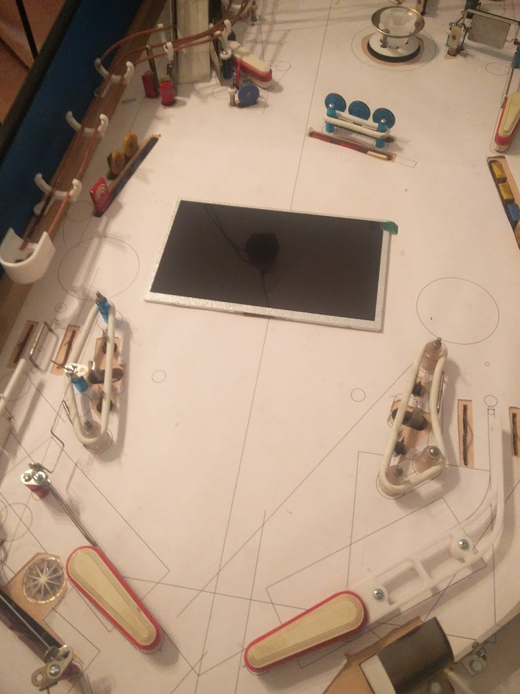
Finally tracked down my weak flipper issue... I replaced the bridge, no change. Replaced the capacitor, no change. Checked signals with a scope, everything looked okay. Cap smoothed the signal out well, peaks were proper height, everything seemed proper. Then I realized... the fuse was blown. I never even considered checking that, since obviously the flippers were working. Something about the way I hooked up two bridges in parallel, one with a smoothing capacitor on it, must have allowed enough voltage to build up through just one side of the AC, through a common ground or something, that allowed it to still get the flippers enough power to flip. Not really sure how that could be, but. I thought I had replicated the circuit gottlieb used on black hole accurately, but the one difference was that I had a separate fuse for each bridge (although I only fused one side of the inputs) while Gottlieb had a shared fuse for both bridges.
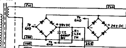
I assumed that was just a cost saving measure, but maybe it's actually because of this?![]()
I also realize now, looking at the schematics, that they don't actually fuse the DC side of the bridge, which is interesting. I guess they figure that the per-coil fuses will usually catch those issues? I guess they usually do, at least in my experience. I definitely didn't fuse my solenoids enough overall. I put separate fuses for each flipper and bumper, but the controlled coils only have the one shared fuse on their driver board. More concerningly, I've never blown the on-board fuses for some reason, but I have blown the rectifier fuse when a coil locked on, despite the rectifier fuse being 8A slow blow and the on-board being a 4A fast blow. Hopefully that doesn't become an issue.
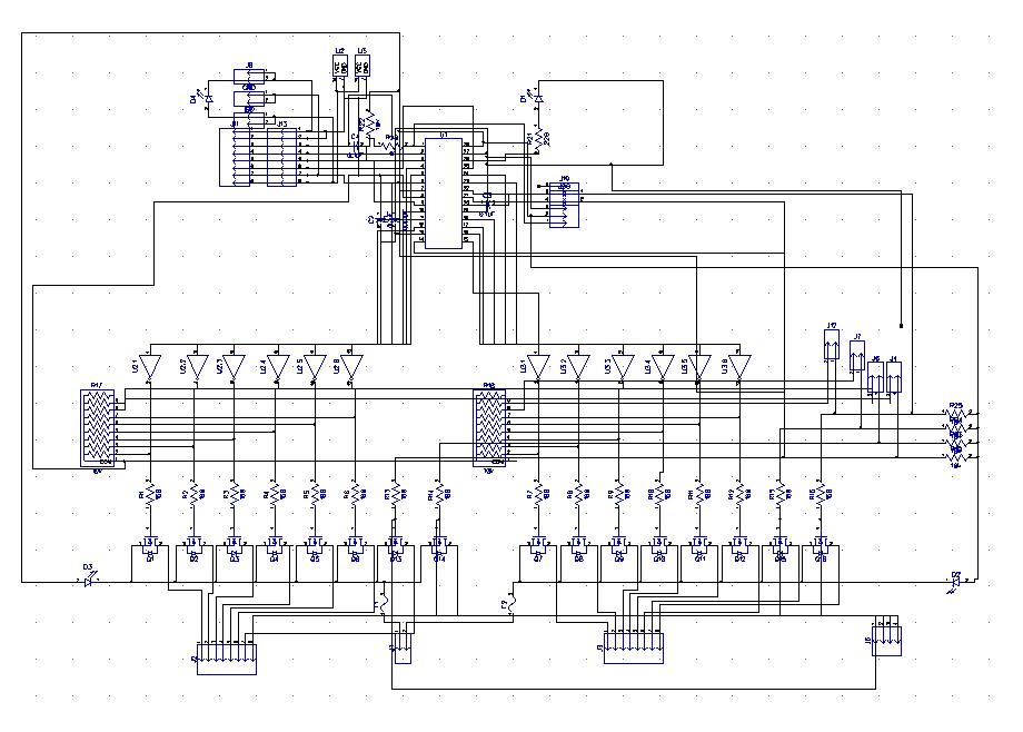
I've also designed another iteration of my driver board since my rev 7 that I assembled still had mistakes, though I haven't ordered it yet since I'd like to get some more boards done for a combined shipment. This time, I restarted from scratch. My previous schematic had been carried over and repeatedly modified since my original rev 1 board back when I started learning how to design boards, and was a bit of a mess.
Before: ![]()
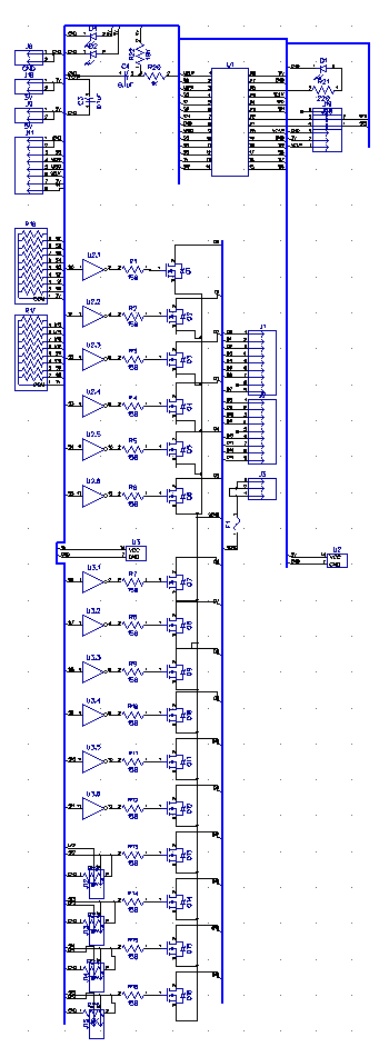
After:![]()
I'd also been repeatedly running into issues when designing the boards trying to fit them in a 2x4" footprint. Over time I went from 13 FETs to 16, added driver chips, fuses, test points, indicator LEDs, etc while still using the same size board, and it had gotten really hard to layout. This time I scrapped the voltage indicator LEDs, and dropped from two fuses (one for each bank of 8 drivers) to one fuse. Originally, I had designed the board so each bank could be operated completely separately, and could be configured with pullups for PNP transistors or pulldowns for NPN transistors, so that it could also be used to drive an 8x8 lamp matrix, but that use has sorta disappeared in the intervening years.
Those part removals combined with some tricky layouts let me finally get all the transistors layed out neatly. This also means that I can now stick both solenoid connectors on one side, and keep all the low voltage signals on the other side of the board, to clean up the wiring a bit more
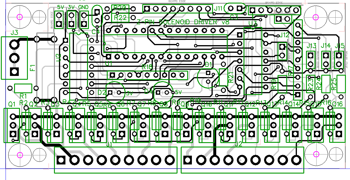
Rev 7: ![]()
Rev 8: ![]()


blog comments powered by Disqus